Demisting device in natural gasification station

A defogging device and natural gas technology, applied in chemical instruments and methods, gas/liquid distribution and storage, separation methods, etc., can solve the problem that the extraction method cannot be fundamentally eliminated, the air in the storage and distribution station is not easy to circulate, and the station personnel Potential safety hazards and other issues, to achieve the effect of improving the heating effect, reducing the cost of defogging, and eliminating the problem of fog

Pending Publication Date: 2022-07-29
珠江燃气集团有限公司
View PDF1 Cites 0 Cited by
  • Summary
  • Abstract
  • Description
  • Claims
  • Application Information

AI Technical Summary

Benefits of technology

The purpose of this new technology was created when it used an opto-electronics system that uses solar energy instead of burning fossil fuels like oil or coal. This could help reduce emissions from vehicles without causing any harmful fumes during their operation.

Problems solved by technology

This patented describes how it can safely store and distribute gases like methane (NG) by providing a specialized facility called Gasator Defrost System(GFD). However, there may also occur situations where mist or other harmful substances from the surrounding environment enter into GDF's container causing fires if they get inside. These issues require further investigation before being able to open up again after use without having any significant health risks associated with them.

Method used


Image

  • Demisting device in natural gasification station
  • Demisting device in natural gasification station
  • Demisting device in natural gasification station

Examples


Embodiment 1

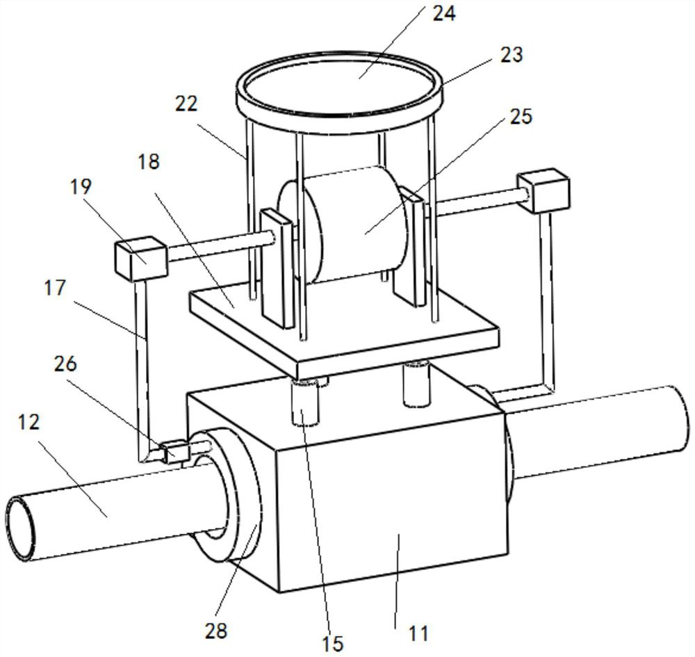
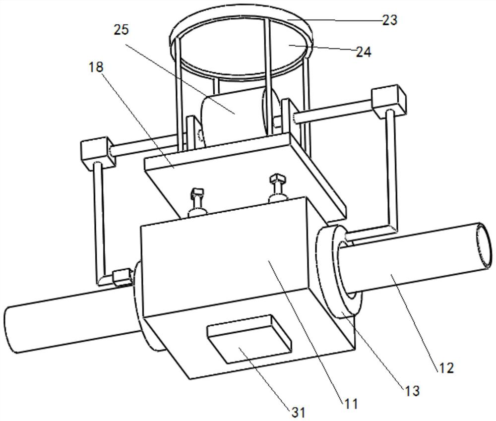
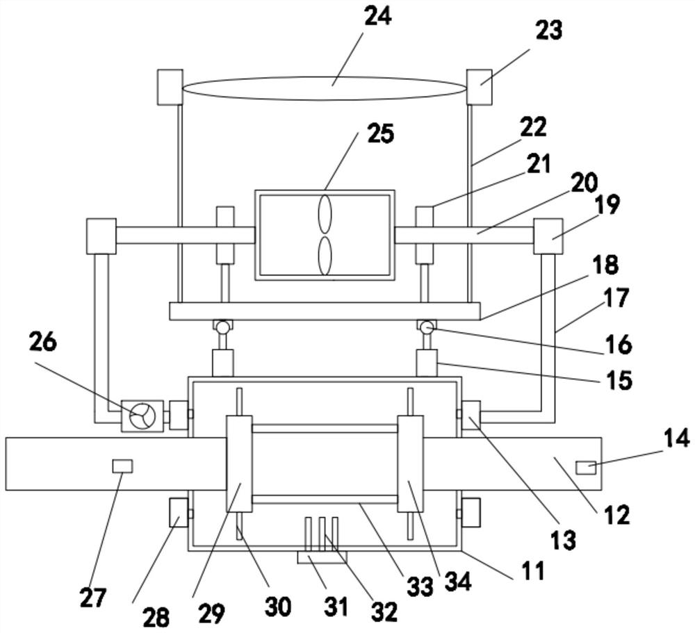
[0023] see Figure 1-Figure 4 , In the embodiment of the present invention, a demisting device in a natural gas chemical station includes a natural gas transmission cylinder 12 for transmitting low-temperature natural gas, and a heating box 11 for providing heat is provided on the outside of the natural gas transmission cylinder 12. The heating box The natural gas transmission cylinder 12 inside 11 is provided with a heat exchange element for increasing the heat exchange area, a mounting seat plate 18 is provided above the heating box 11, and a mounting seat plate 18 is provided above the mounting seat plate 18 for connecting with the heating box. 11. A solar heating assembly for heat exchange, the solar heating assembly communicates with the outside of the heating box 11 through a liquid guide hose 17, and the liquid guide hose 17 is provided with a circulating pump 26 for promoting fluid circulation. The solar heating assembly provides heat energy for the heating box 11, thereb


PUM


Abstract

The in-station demisting device comprises a natural gas conveying cylinder used for conveying low-temperature natural gas, a heating box used for providing heat is arranged on the outer side of the natural gas conveying cylinder, and a heat exchange piece used for increasing the heat exchange area is arranged on the portion, in the heating box, of the natural gas conveying cylinder. A mounting seat plate is arranged above the heating box, a solar heating assembly used for conducting heat exchange with the heating box is arranged above the mounting seat plate, and the solar heating assembly communicates with the outer side of the heating box through a liquid guide hose. A heat source is provided by designing a photovoltaic heating mode, the heating effect is improved in cooperation with a light gathering and angle adjusting mode, it can be guaranteed that gasified natural gas is effectively heated, therefore, the mist problem is solved, the demisting cost is reduced, and practicability is high.

Description


Claims


Application Information

Patent Timeline
Owner 珠江燃气集团有限公司
Why Eureka
Try Eureka