Two-carbon accumulator

A technology for storage batteries and carbon electrodes, which is applied in the manufacturing of alkaline storage batteries, secondary batteries, sustainable manufacturing/processing, etc. The effect of short charging time and low price

Inactive Publication Date: 2004-09-08
上海洲益电源有限公司 +1
View PDF0 Cites 2 Cited by
  • Summary
  • Abstract
  • Description
  • Claims
  • Application Information

AI Technical Summary

Benefits of technology

The present inventors have been working on improving the performance of batteries by adding certain substances that help them work better during charge/discharges. These improvements include reducing or eliminating any harmful side products from their cells while still allowing for longer lifetimes due to less expensive raw components used instead of metallic ones like silver cathodes. Additionally, they suggest making these new types of batterys faster because it doesn't require much energy compared to older designs which use pure copper anode plates.

Problems solved by technology

This patents describes different types of accumulator systems that can be used for generating electricity from certain substances like water or other liquids. These systems require an external source of energy to operate effectively. However, they also produce harmful waste products during operation due to the consumption of these resources. Additionally, some older devices may lose performance overtime by having issues with the ability to charge them properly.

Method used


Image

  • Two-carbon accumulator
  • Two-carbon accumulator
  • Two-carbon accumulator

Examples


Embodiment Construction

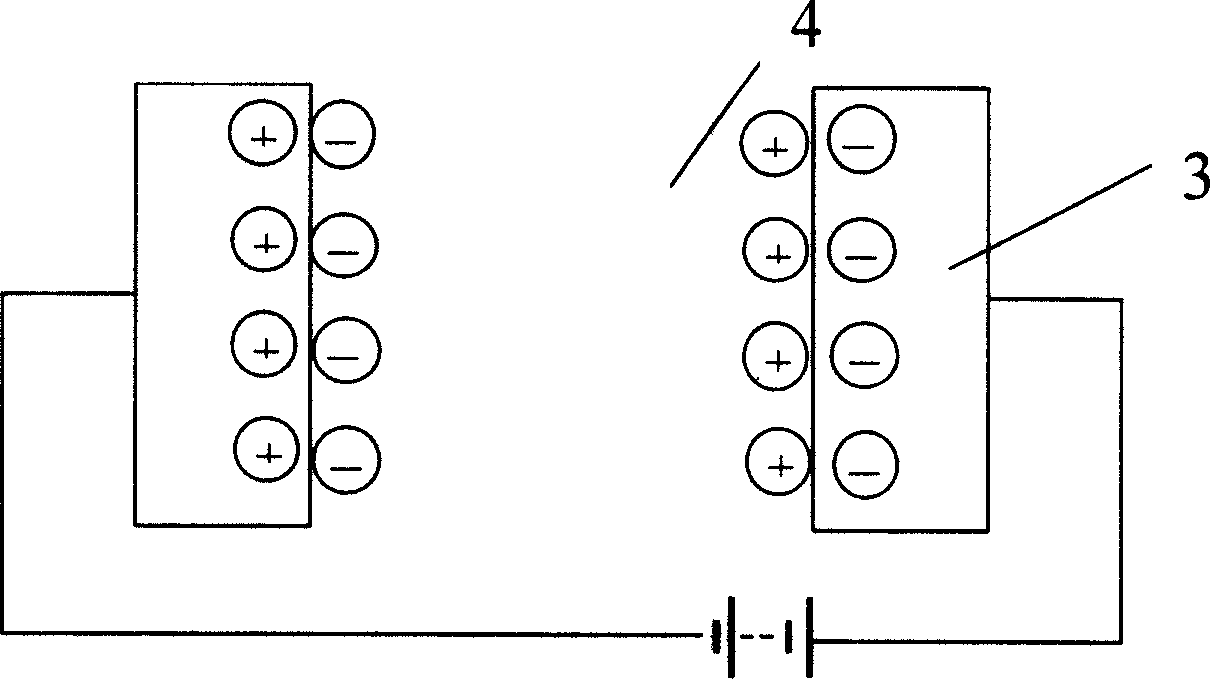
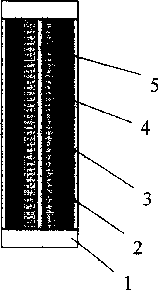
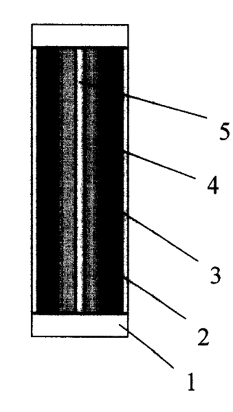
[0014] Such as figure 1 and figure 2 As shown, the present invention is a dual-carbon storage battery, said dual-carbon storage battery is composed of at least one pair of carbon electrodes 3 and an electrolyte 4, and is characterized in that an electrolyte is arranged between any pair of carbon electrodes 3 4. Any pair of carbon electrodes 3 includes an anode and a cathode, and a diaphragm 5 is arranged between any pair of carbon electrodes 3, and the diaphragm 5 divides the electrolyte 4 into two parts, so The carbon electrode 3 described above can also be connected with a collector plate 2. When processed into a product, both ends of the carbon electrode 3 and the electrolyte 4 are packaged with the encapsulation portion 1, and the electrolyte 4 can be a liquid It can also be solid, and potassium hydroxide solution is generally used.

[0015] When charging, the collector plate is connected to an external power source, under the action of an electric field, and due to ioniza


PUM


Abstract

The double-carbon accumulator consists of at least one pair of carbon electrodes and electrolyte, and features that electrolyte is set between two carbon electrodes of each pair. Under the action of the electric field and ionization, the positive charges and the negative charges move to the surface of the carbon electrodes separately to form charge layers and realize charging. The present invention has long service life, no environmental pollution, short charge period, low cost, no polarity and great discharge current.

Description


Claims


Application Information

Patent Timeline
Owner 上海洲益电源有限公司
Why Eureka
Try Eureka