Digitization manufacture multifunctional assistance control system

An auxiliary control system and multi-functional technology, applied in the computer field, can solve the problems of resource waste, communication rate restriction, unstable work, etc., and achieve the effects of improving the utilization rate, shortening the production preparation time, and improving the operation efficiency.

Inactive Publication Date: 2006-01-18
中国兵器工业第五五研究所
View PDF0 Cites 0 Cited by
  • Summary
  • Abstract
  • Description
  • Claims
  • Application Information

AI Technical Summary

Benefits of technology

This patented technology allows companies in different industries to share data with each other more efficiently during their businesses' operations. It simplifies the way they work together and improves overall performance without sacrificing accuracy.

Problems solved by technology

This patented describes different ways in which computers have been used over networks due to their ability to communicate data wirelessly between devices without requiring physical connections or complex operations. However, current methods require both machines (workstations), servers, and clients to perform certain functions simultaneously at once, making them difficult to use effectively across multiple platforms.

Method used


Image

  • Digitization manufacture multifunctional assistance control system
  • Digitization manufacture multifunctional assistance control system

Examples


Embodiment Construction

[0022] The present invention will be further described below in conjunction with accompanying drawing:
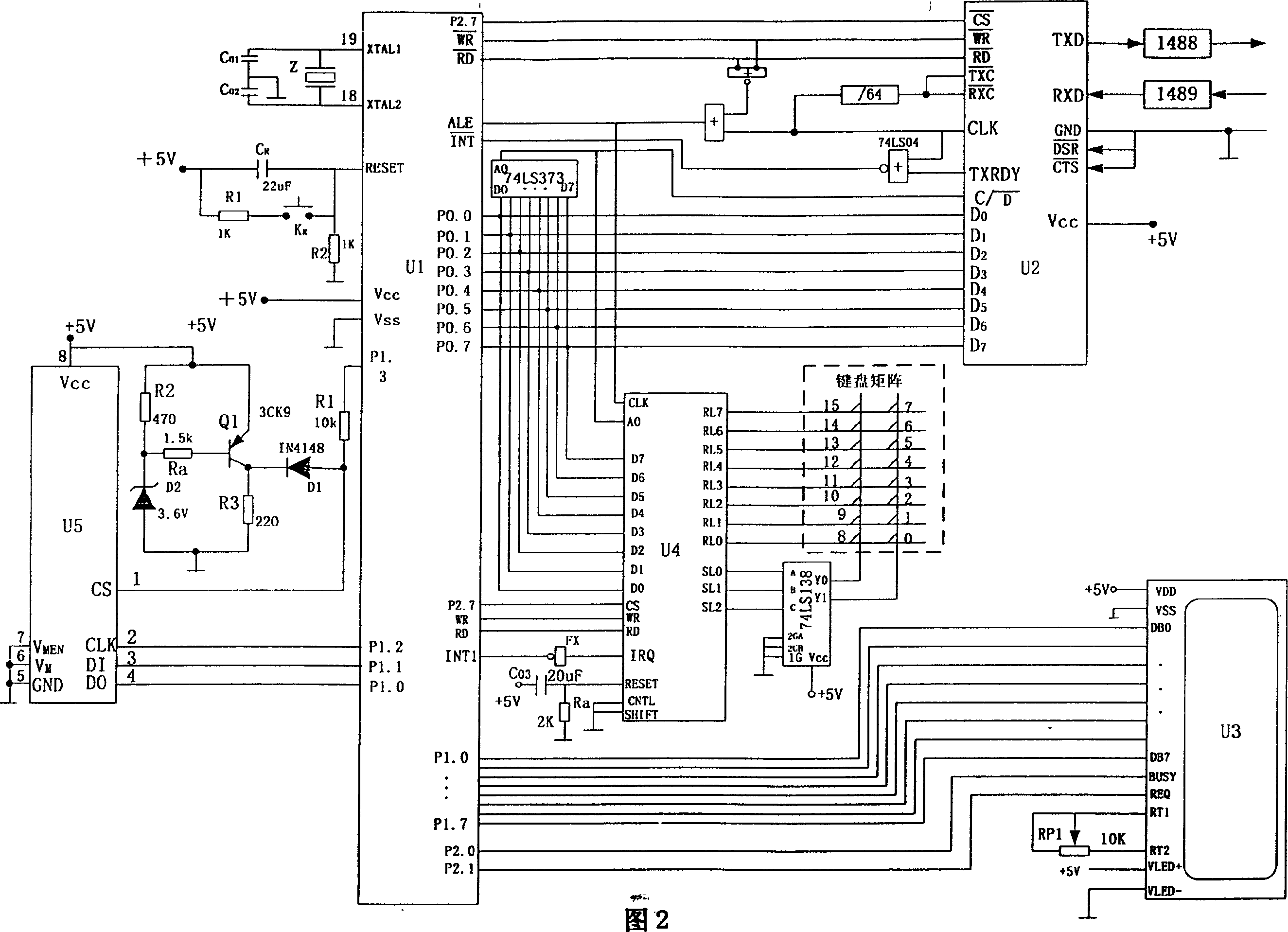
[0023] 1) U1 unit

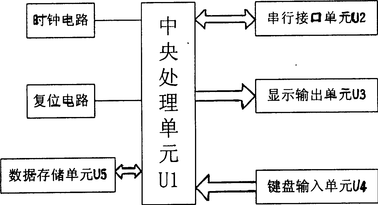
[0024] U1 unit includes system clock circuit, reset circuit and CPU chip, which is the core part of the system.

[0025] The system clock circuit utilizes the oscillator circuit inside the chip, connects an external crystal oscillator to XTAL1 and XTAL2 pins, and forms a parallel oscillation circuit with capacitors C01 and C02. In order to make the oscillator have higher frequency stability, a 70pF NPO capacitor is used.

[0026] The reset circuit adopts a power-on and button reset circuit. At the moment of power-on, the RC circuit is charged, and a positive pulse appears at the RESET pin. As long as the RESET pin maintains a high level for more than 10ms, the system can be effectively reset.

[0027] The CPU pin function is divided into user I / O, control bus, data bus and address bus, among which the 16-bit address bus is provided by the P0 port through


PUM


Abstract

The invention relates to a digital making multi-function control system, which relates to an improved computer network and communication in the field of mechanism industry. It has the following characters: time circuit is the time of all the system work, which uses crystal oscillator and electric capacity to lead CPU U1 system by interlock XTAL1.XTAL2; reset circuit adopts giving electricity and press key reset mode; series interface unit U2 adopts D0-D7 octet data bit and CPU U1 communication; display output unit U3 communicates with CPU U1 by DB0-DB7; input unit U4 is formed by keyboard array and input chips; keyboard array communicates with input chips by RL0-RL7; D0-D7 of input chips communicate with CPU U1.

Description


Claims


Application Information

Patent Timeline
Owner 中国兵器工业第五五研究所
Why Eureka
Try Eureka