Quartz type pressure sensor, and production method therefor

A pressure sensor, quartz technology, applied in the direction of fluid pressure measurement using capacitance change, etc., to achieve the effect of increasing production, small changes over time, and improving processing accuracy

Inactive Publication Date: 2006-08-02
SEIKO EPSON CORP
View PDF2 Cites 15 Cited by
  • Summary
  • Abstract
  • Description
  • Claims
  • Application Information

AI Technical Summary

Benefits of technology

This patented technology uses different types of glass called quartz or other similar substances like sapphire because they have very good physical stability but lacked flexibility when being worked into shapes. By replacing these traditional methods such as cutting crystal plates, we found better results than previous techniques. Additionally, our sensors were able to measure both pressures and produce accurate measurements even at small changes in their properties caused by temperature fluctuations during operation. Overall, this new method provides technical benefits including precise measurement, reduced variation across multiple samples, enhanced durability, and more reliable performance.

Problems solved by technology

Technological Problem: Current Air Pulse Inflation Tester Systems use Ceramic or Platinum Resistors as their detection element but they suffer from poorer performance than expected because it cannot accurately measure changes caused by small variations in atmospheric conditions during driving cycles without causing false alarms.

Method used


Image

  • Quartz type pressure sensor, and production method therefor
  • Quartz type pressure sensor, and production method therefor
  • Quartz type pressure sensor, and production method therefor

Examples


Embodiment Construction

[0062] Embodiments of the present invention shown in the drawings will be described in detail below.

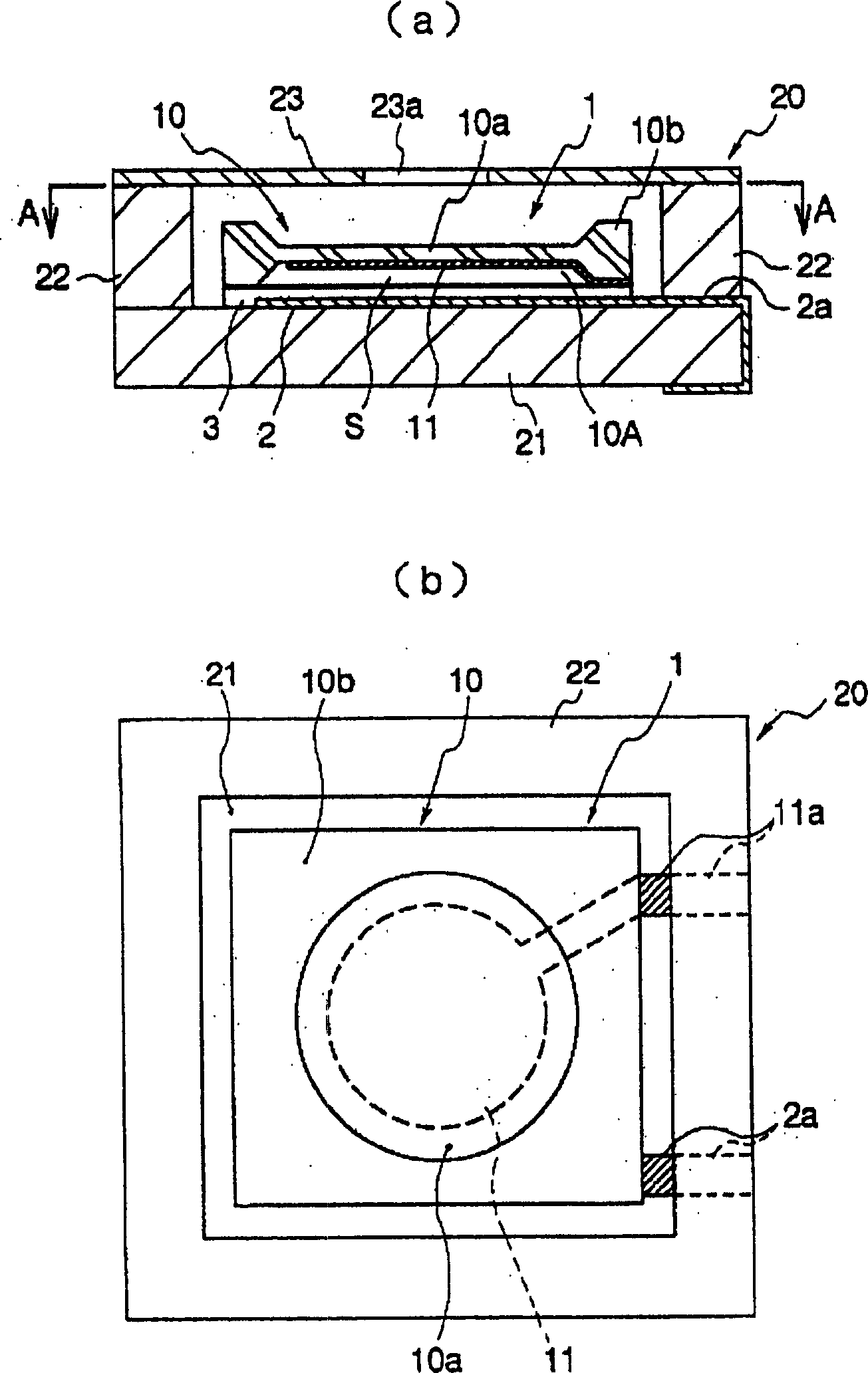
[0063] figure 1 (a) and 1(b) are vertical sectional views showing the overall structure of the contact mode capacitive pressure sensor according to an embodiment of the present invention, and figure 1 (a) A sectional view taken along the line A-A shown.

[0064] A contact mode capacitance type pressure sensor (hereinafter referred to as "pressure sensor" or "contact mode type pressure sensor") 1 is accommodated in a container 20 made of an insulating material such as ceramics. The ceramic container 20 generally includes a bottom plate 21, four side walls 22 erected from the periphery of the bottom plate 21, and an upper cover 23 fixed to the upper opening formed by the side walls 22 and provided with a vent hole 23a.

[0065] Since the side wall 22 and the upper cover 23 are not necessary, a structure in which the detection sheet 10 and the like are assembled on the bottom p


PUM


Abstract

In a touch-mode capacitance type pressure sensor, a quartz pressure sensor that can solve difficulty in thickness control on a diaphragm due to a low etching precision which is a drawback in a pressure sensor using a detecting piece made from silicon, and deterioration in a detecting accuracy and poor repetitive reproducibility in elastic deformation due to the difficulty, respectively, is provided by utilizing quartz as a detecting piece for the pressure sensor. The quartz pressure sensor includes a bottom plate made from an insulating material, a lower electrode film and a dielectric film sequentially laminated on a face of the bottom plate, a detecting piece provided at a position thereof opposed to said dielectric film with a thin portion and fixed on the face of the bottom plate, and an upper electrode film formed in at least one portion of the thin portion having a positional relationship thereof opposed to the lower electrode film, in which a fine gap airtight space is provided between a lower face of the detecting piece and the dielectric film is characterized in that the detecting piece is made from a quartz material.

Description


Claims


Application Information

Patent Timeline
Owner SEIKO EPSON CORP
Why Eureka
Try Eureka