Wheel carrier for a two-track motor vehicle

a two-track motor vehicle and wheel carrier technology, applied in suspensions, vehicle springs, resilient suspensions, etc., can solve the problem of limiting the rotary adjustment of the angle stop, and achieve the effect of avoiding the limitation of the angle stop

Active Publication Date: 2019-07-16
AUDI AG
View PDF50 Cites 4 Cited by
  • Summary
  • Abstract
  • Description
  • Claims
  • Application Information

AI Technical Summary

Benefits of technology

The technical effect of this patented solution for preventing interference during driving on different types of road surfaces such as snowy roads without causing damage from collision with other vehicles' wheels.

Problems solved by technology

The technical problem addressed in this patented text describes how to design a wheels support system that allows for independent movement or adjustments of both the front and rear bearings without requiring excessive space around them while also ensuring safety against collision damage from external factors like debris impacts.

Method used


Image

  • Wheel carrier for a two-track motor vehicle
  • Wheel carrier for a two-track motor vehicle
  • Wheel carrier for a two-track motor vehicle

Examples


Embodiment Construction

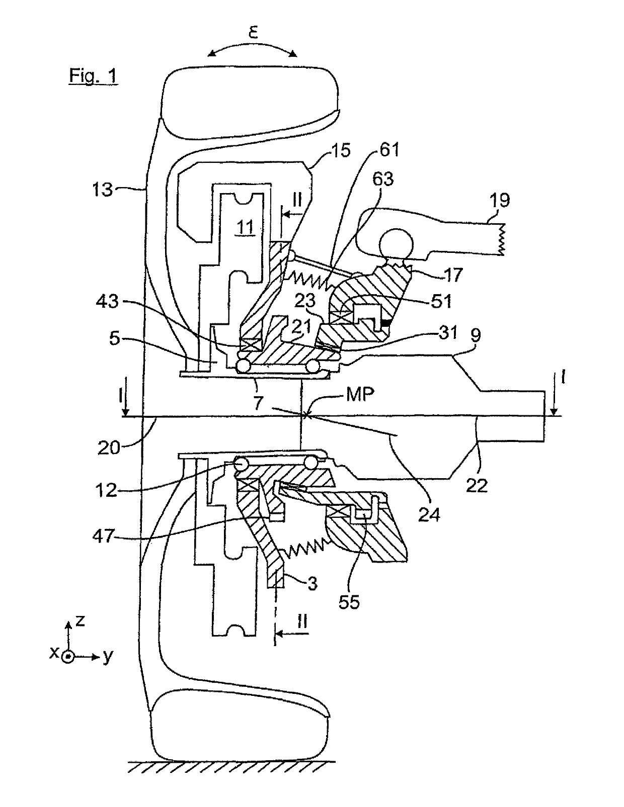
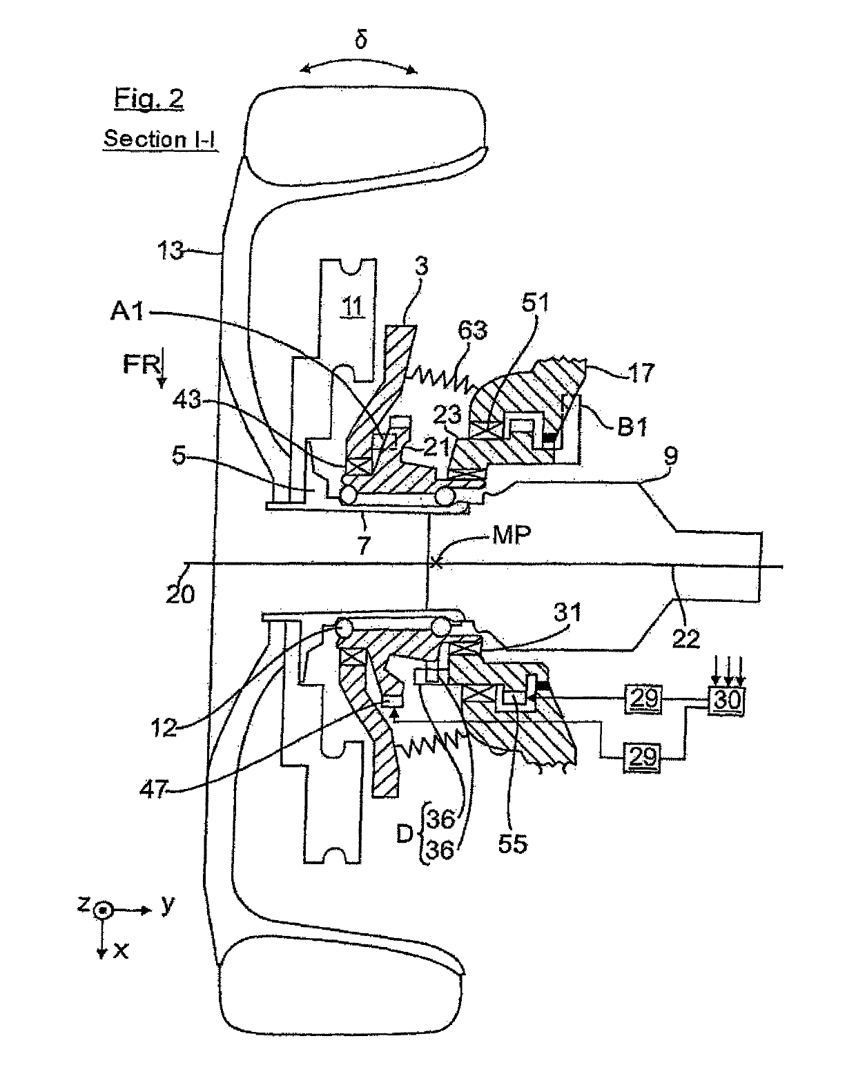
[0030]FIG. 1 shows the wheel carrier with mounted vehicle wheel 13 in a side view. The wheel carrier has a carrier part 3 in which a wheel flange 5 is rotatably supported with its hub section 7 in a wheel bearing 12 with interposition of a bearing 43. On the wheel flange 5 a brake disc 11 and a vehicle wheel 13, via its wheel rim, are mounted. The brake disc 11 together with a brake caliper 15, which is mounted on the carrier part, are a component of the brake system. Through the wheel carrier an articulated shaft, which drives the vehicle wheel 13, is guided, wherein on the constant velocity joint 9 of the articulated shaft an also not shown central screw is screwed with which the wheel bearing 12 is clamped via the wheel hub 5 and the constant velocity joint 9.

[0031]The wheel carrier also has a guide part 17 on which in FIG. 1 exemplarily a control arm 19 of the wheel suspension is articulately connected. Between the carrier part 3 and the guide part 17 two rotary parts 21, 23 are pr


PUM


Abstract

A wheel carrier for a two-track motor vehicle including a wheel-side carrier part, which carries a vehicle wheel; an axle-side guide part; axle-side rotary parts arranged between the wheel-side carrier part and the axle-side guide part and supported on a common bearing site for rotation relative to each other about a rotation axis by respective rotation angles, wherein the carrier part is pivotable about the rotation axis about a pivot point for toe and/or camber adjustment of the vehicle wheel by rotation of at least one of the rotary parts by the respective rotation angle into a rotary position, which correlates with a toe and/or camber angle of the vehicle wheel, wherein the toe and/or camber angle being arbitrarily adjustable within a toe and/or camber angular range. The wheel carrier further includes at least one movement stop adapted for limiting the toe and/or camber angular range of the vehicle wheel.

Description


Claims


Application Information

Patent Timeline
Owner AUDI AG
Why Eureka
Try Eureka