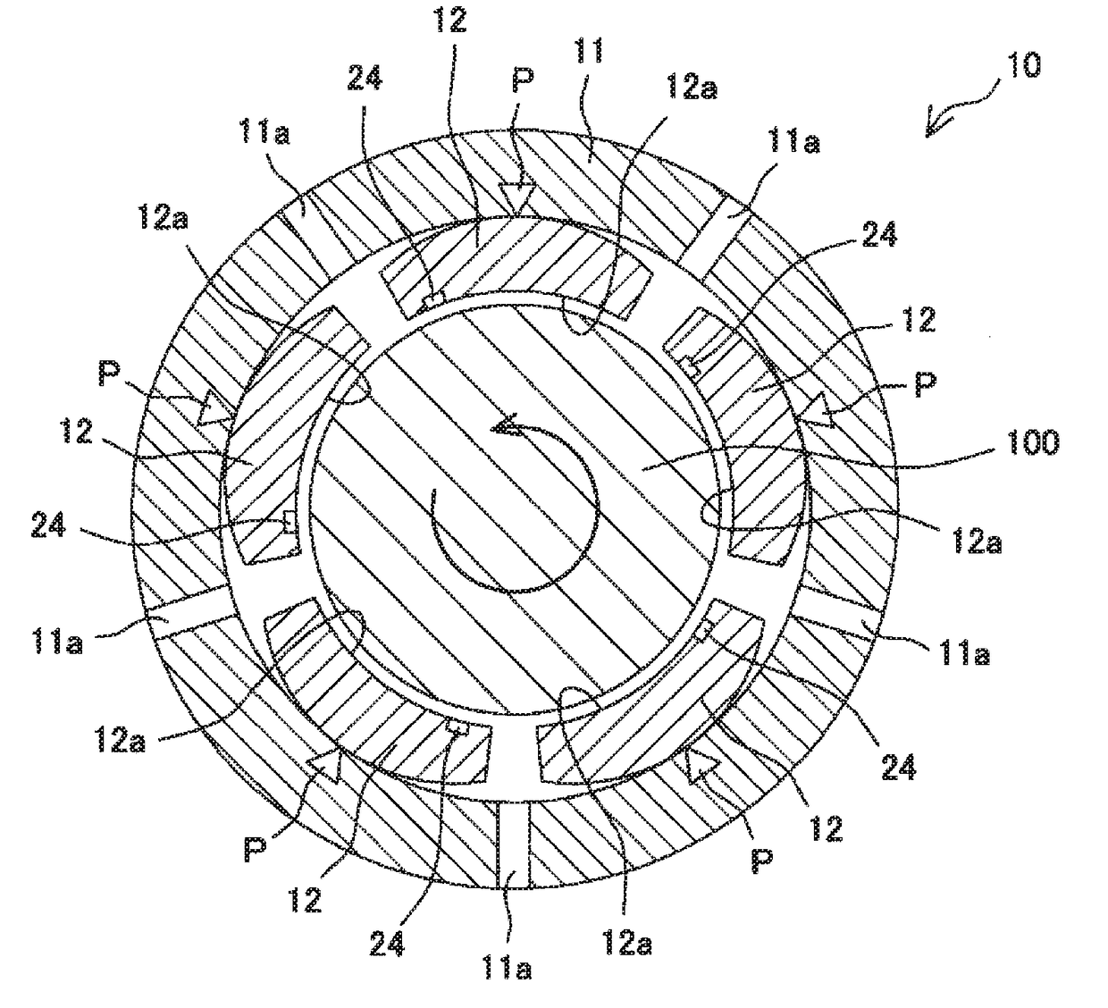
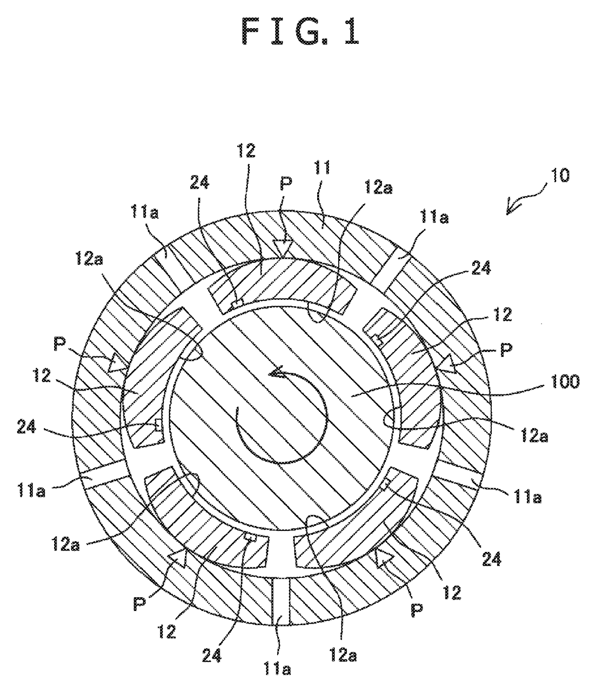
Tilting pad journal bearing
a journal bearing and tilting pad technology, applied in the direction of bearings, shafts and bearings, rotary bearings, etc., can solve the problems of deterioration of the load supporting capacity of the bearing or the effect of vibration suppression by an oil film, and achieve the effect of suppressing the increase of the temperature of the opposite surface of the pad, and reducing the impact for
- Summary
- Abstract
- Description
- Claims
- Application Information
AI Technical Summary
Benefits of technology
Problems solved by technology
Method used
Image

Examples
modified example
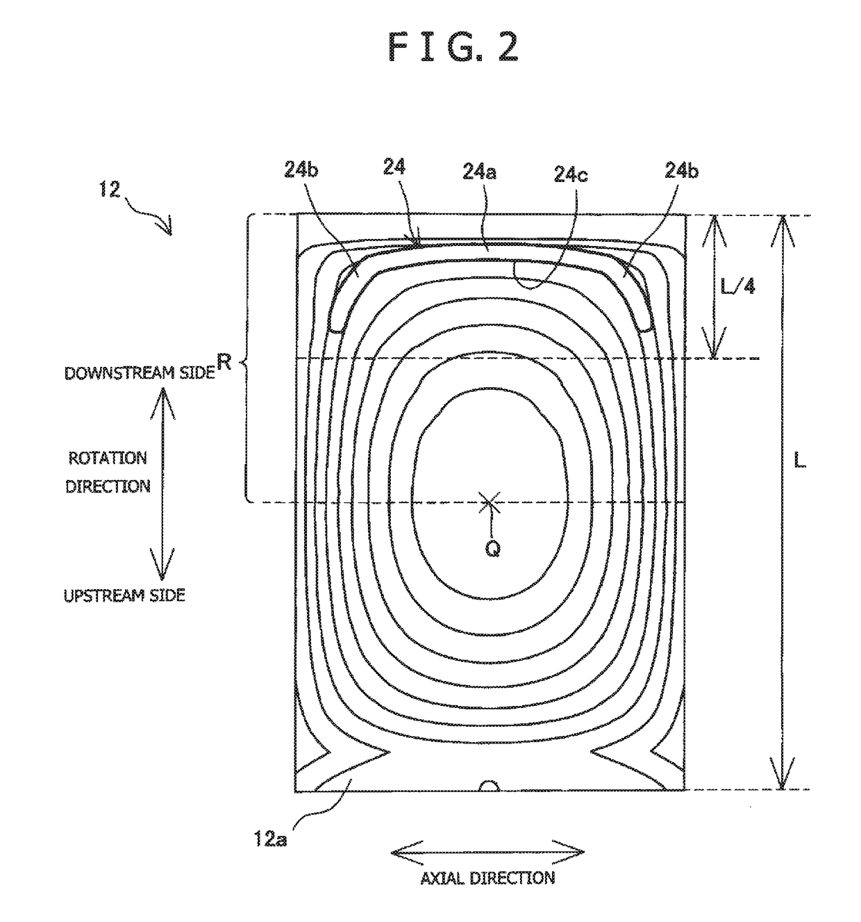
[0040]In the embodiment described above, the single oil supply groove 24 formed along the isopleth is provided as “the oil supply unit” of the present invention; however, the oil supply unit may not have to be configured in such a manner. For example, the oil supply unit may be configured as in respective modified examples described below. Explanations of common configurations to the foregoing embodiment r to the respective modified examples are omitted as appropriate. Also, explanations of effects achieved by the common configurations are omitted as appropriate.
[0041]As shown in FIG. 5, plural oil supply grooves 25, 26 (here, two oil supply grooves) parallel to each other may be provided as “the oil supply unit” of the present invention. Here, it is not necessary that the oil supply grooves are exactly parallel to each other. The oil supply grooves 25, 26 may be substantially parallel to each other without intersecting with each other. The plural oil supply grooves 25, 26 are provided
PUM
 Abstract
Description
Claims
Application Information
 - R&D Engineer
- R&D Manager
- IP Professional
- Industry Leading Data Capabilities
- Powerful AI technology
- Patent DNA Extraction
Browse by: Latest US Patents, China's latest patents, Technical Efficacy Thesaurus, Application Domain, Technology Topic.
© 2024 PatSnap. All rights reserved.Legal|Privacy policy|Modern Slavery Act Transparency Statement|Sitemap