Axial-mode linear wind-trubine

Inactive Publication Date: 2002-04-11
RAGNER GARY DEAN
View PDF0 Cites 196 Cited by
  • Summary
  • Abstract
  • Description
  • Claims
  • Application Information

AI Technical Summary

Problems solved by technology

Many lighter-than-airships have been proposed for collecting this energy; but lifting an entire windmill and generator into the sky is expensive at best.
These large airships are also susceptible to damage even in mildly strong winds making this type of system an extremely uneconomical method of collecting the wind energy.
This operating criteria greatly limit the amount of energy collected because the kite must move generally in the direction of the wind.
Lois, Loeb, and Carpenter instead shows a slow-speed (slower than wind speed) wind energy device that uses DRAG to produce power, but does not control the wing to induce high-speed flight, or flight perpendicular to the wind.
This adds bulk to the airborne portion of the system and makes it more difficult to keep aloft.
This is true for kites with fixed lines connected to a static point on the ground, but it is completely unknown technology on how to co

Method used


Image

  • Axial-mode linear wind-trubine
  • Axial-mode linear wind-trubine
  • Axial-mode linear wind-trubine

Examples


Embodiment Construction

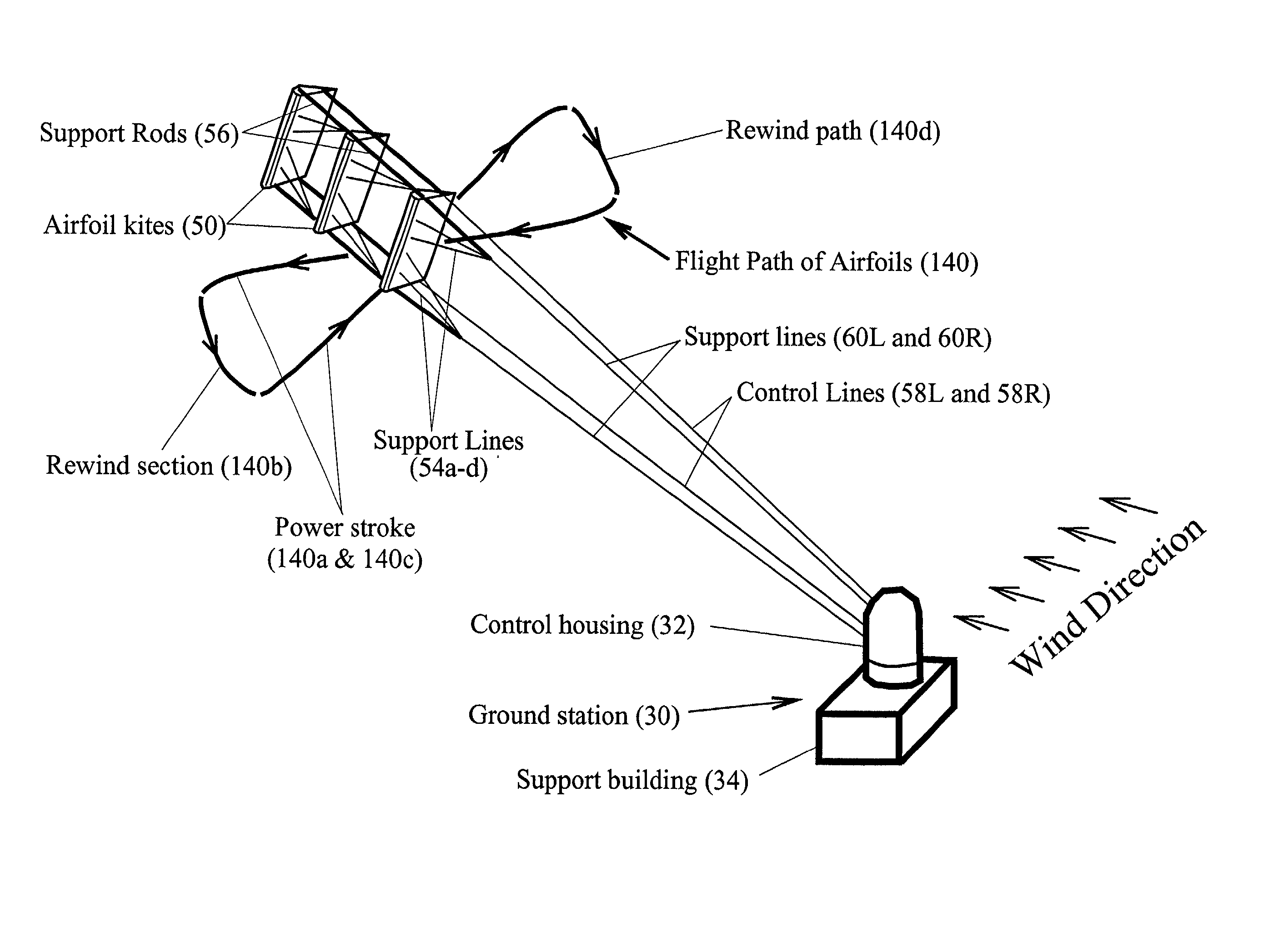
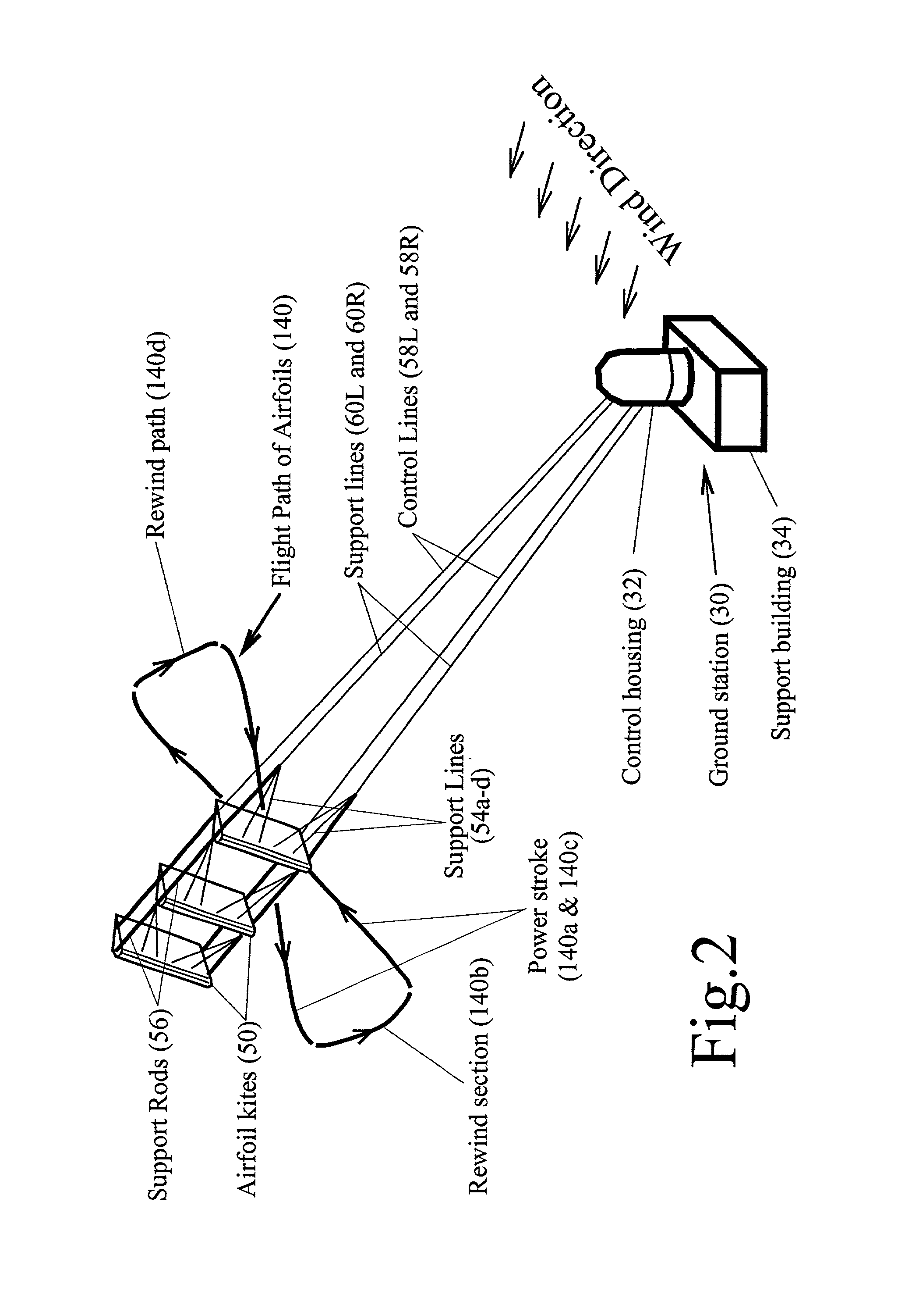
[0022] Before we go into great detail of the preferred embodiments, we should consider some of the physical properties involved which govern the operation of this type of turbine kite system. At this time it is sufficient to understand the general design for the turbine kite from FIG. 2. This system consists of three airfoil kites 50 in tandem which are attached to the Ground Station 30 by support lines 60L and 60R, and control lines 58L and 58R (collectively the support lines and control lines will be referred to throughout this patent as control lines). By controlling the differential length of these control lines, the airfoil's direction and speed can be controlled from the ground to follow the shown Flight Path. The control lines are also directly connected to a shaft and pulley system (see FIG. 12) in the Ground Station 30. As the Airfoil Kites 50 are propelled by the wind at very high speed, all four control lines are reeled-out under tremendous force causing the pulley and shaft


PUM


Abstract

A wind harnessing system using a plurality of self supporting airfoil kites 50 for useful power. The system comprising multiple airfoil kites 50 in tandem attached to a pivotal control housing 32 by control lines 58L and 58R and support lines 60L and 60R. Control lines 58L and 58R can change length with respect to the length of support lines 60L and 60R to control the airfoil kites' 50 angle-of-attack, pitch angle, direction of flight, and flight speed. The length of control lines 58L and 58R are controlled from ground station 30 by a movable pulley system in control housing 32 to adjust the airfoils' direction to follow a specific flight path 140. Control lines 58R and 58L and support lines 60R and 60L are also wound on a power shaft and pulley system in control housing 32. As the airfoil kites are propelled by the wind at very-high speed, the airfoils generate a powerful AXIAL force. The control lines 58L and 58R and support lines 60L and 60R are then reeled-out under this AXIAL tension causing the power shaft and pulley system in control housing 32 to turn a generator to generate electricity. After airfoil kites 50 have finished their reel-out power stroke 140a, the airfoil's pitch angle is greatly increased so they can be reeled-in by their control and support lines using a minimum of force along path 140b. Once the airfoils have been rewound to the proper distance, the airfoils are again angled for high-speed operation to generate powerful AXIAL force and reeled-out along 140c to provide another power stroke The airfoil kites are then reeled-in again along path 140d and an the entire process repeats starting with power stroke 140a. Since the force to rewind the airfoils is much less than the force generated during reel-out, there is net power generated.

Description


Claims


Application Information

Patent Timeline
Owner RAGNER GARY DEAN
Why Eureka
Try Eureka