Spray device

Inactive Publication Date: 2005-09-01
SHANGHAI ELECTRICGROUP CORP
View PDF15 Cites 5 Cited by
  • Summary
  • Abstract
  • Description
  • Claims
  • Application Information

AI Technical Summary

Benefits of technology

[0007] An object of the present invention is to provide a spray device fo

Problems solved by technology

Droplets that are too small contribute to misting, and may never reach the surface of the dampening roll.
In addition, droplets that are too large or dense may cause splash-back when they stri

Method used


Image

  • Spray device
  • Spray device
  • Spray device

Examples


Embodiment Construction

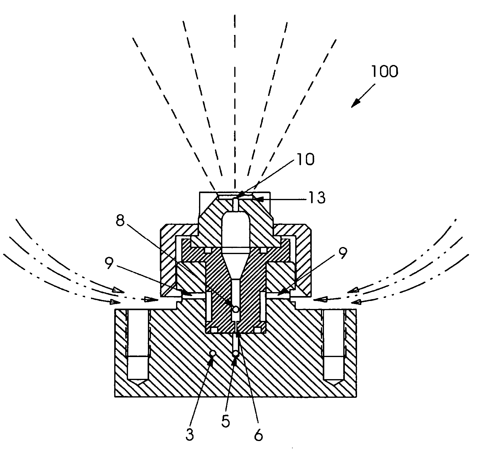
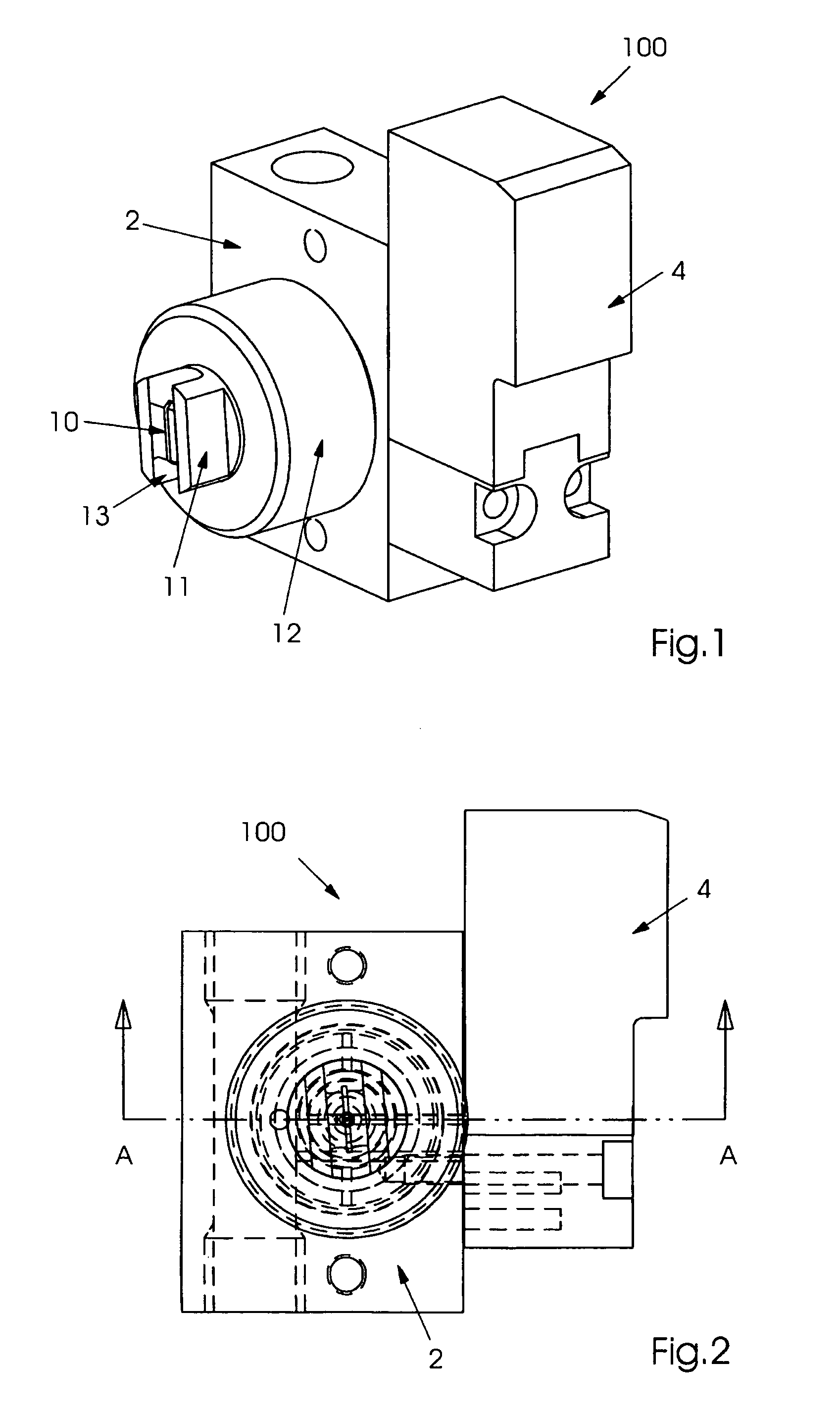
[0028]FIGS. 1 and 2 show an exemplary embodiment of a spray device 100 of the present invention. Screw cap 12 is threaded onto body member 2 and holds nozzle tip 11 in place. Exit orifice 10 is visible on the front on spray device 100 as is flat-bottom slot 13. Solenoid 4 is mounted to the side of body 2 for actuating a valve element 16 inside of solenoid 4, to repeatedly interrupt a flow of liquid through the spray device and cause pulsed spraying.

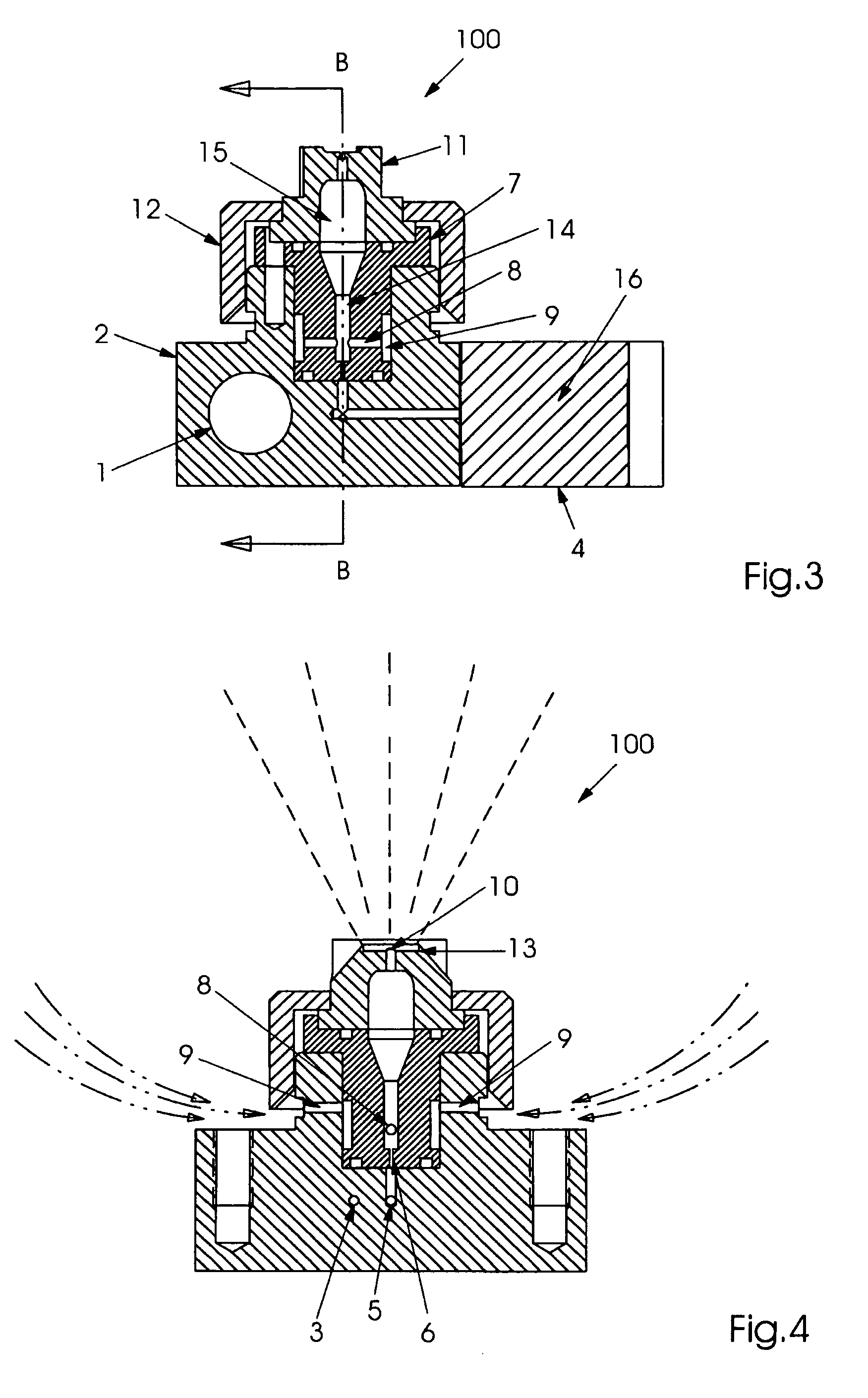
[0029] The paths of the liquid and gas through the spray device are visible in the sectional views of FIG. 3 (showing a sectional view through line A-A of FIG. 1) and in FIG. 4 (showing a sectional view through line B-B of FIG. 3). A liquid enters the body member 2 through liquid supply conduit 1. Where the spray device is used for dampening a plate cylinder on a printing press, the liquid is typically a fountain solution of water that includes additives to reduce its surface tension. In other applications of the spray device, the liquid ma


PUM

PropertyMeasurementUnit
Pressureaaaaaaaaaa
Flow rateaaaaaaaaaa
Sizeaaaaaaaaaa

Abstract

A spray device for a printing press includes a liquid inlet orifice for receiving a liquid, a gas inlet orifice for receiving a gas disposed downstream from the liquid inlet orifice, and an exit orifice disposed at a distance from a surface of the printing press. In addition, a method for applying a liquid to a surface of a printing press, includes the steps of providing a liquid to a liquid inlet orifice of a spray device, providing a gas to a gas inlet orifice of the spray device; and spraying a mixture of the liquid and gas onto the surface of the printing press.

Description


Claims


Application Information

Patent Timeline
Owner SHANGHAI ELECTRICGROUP CORP
Why Eureka
Try Eureka