Air-purifying device for a front-opening unified pod

a technology unified pod, which is applied in the field of air purification device, can solve the problems of insufficient moisture and chemical gas, insufficient sealing performance of foup, and inability to be used in practi

Inactive Publication Date: 2005-12-08
CAMBRIDGE FILTER JAPAN +2
View PDF6 Cites 6 Cited by
  • Summary
  • Abstract
  • Description
  • Claims
  • Application Information

AI Technical Summary

Benefits of technology

This patented technology describes an improved way to remove unwanted substances such as dirt or water vapor during indoor ventilation without affecting their quality. It uses fans driven by a motor system to crush any debris found within them before they enter the machine's interior space. Dust filters can be used instead of traditional bags made up mostly of plastic material to help prevent damage caused by small particles like pollen grains. Chemically filtering agents also work well at reducing harmful gas levels produced when burning fossil fuels. By doing this, there will be less pollution generated compared to current methods while still maintaining good efficiency.

Problems solved by technology

Technological Problem: Miniature electronic devices require smaller spaces than traditional systems due to their high cost per unit volume. To address this issue, there was introduced a new method called vacuum packaging technology where small packages with various technical features can be placed into containers made up of plastic or metal instead of glass. These techniques aim to reduce environmental concerns by removing unwanted substances such as water vapor and gaseous pollutants while maintaining product quality standards.

Method used


Image

  • Air-purifying device for a front-opening unified pod
  • Air-purifying device for a front-opening unified pod
  • Air-purifying device for a front-opening unified pod

Examples


first embodiment

the Invention

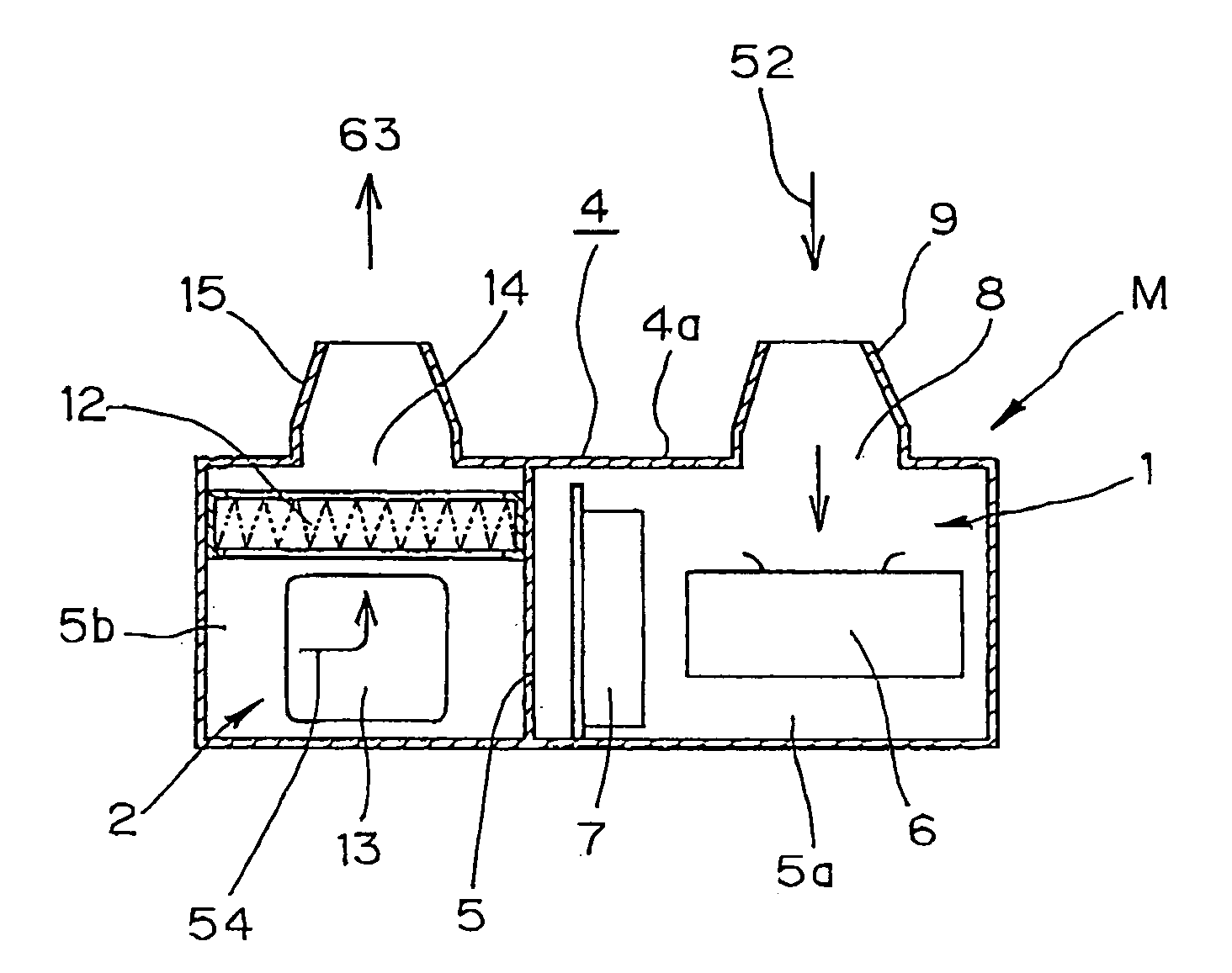
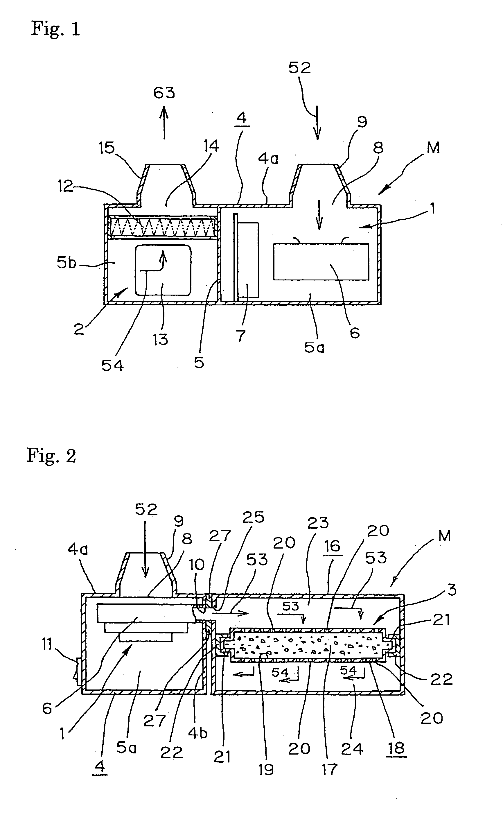
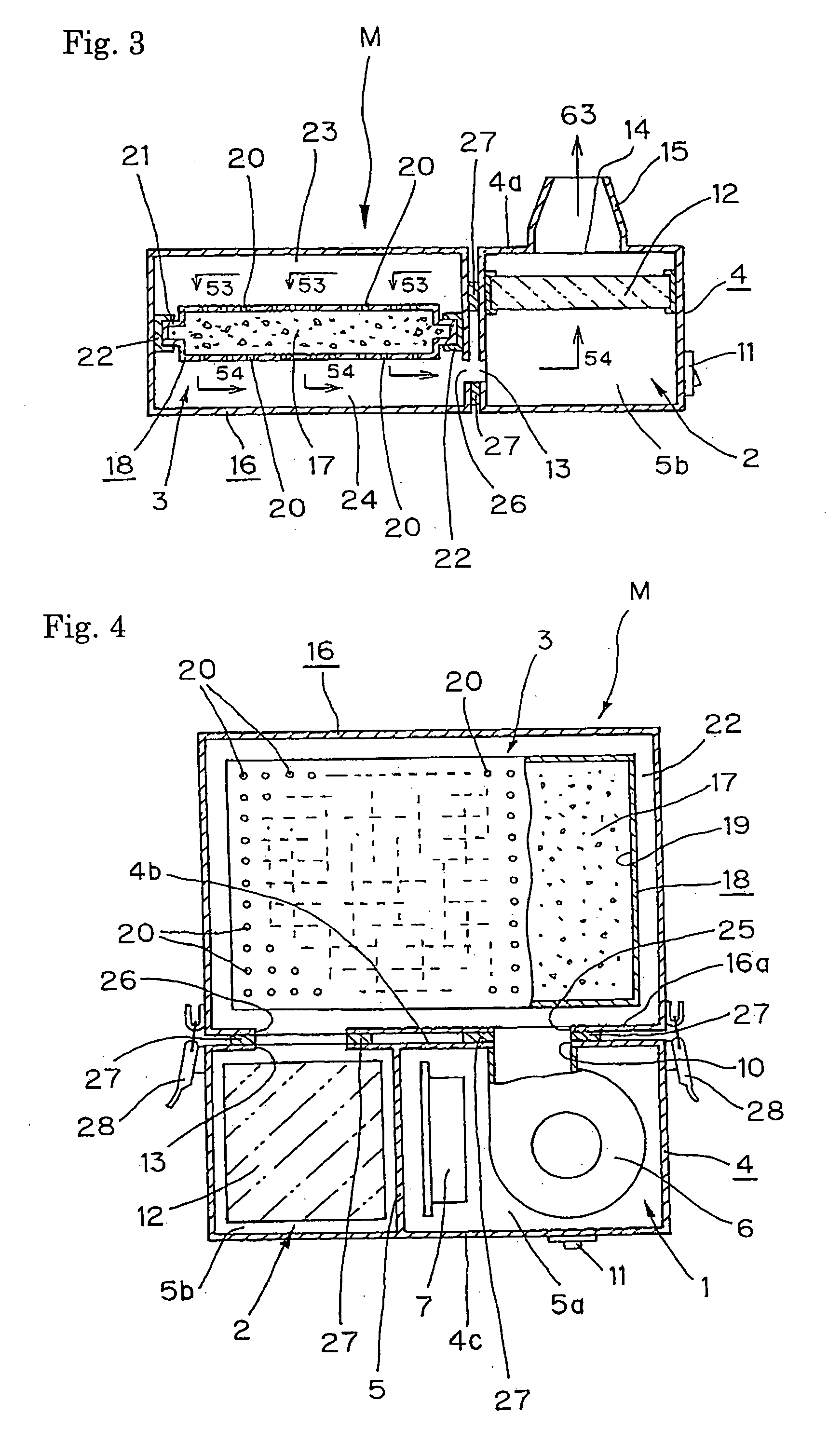
[0020] In reference to FIGS. 1-4, the first embodiment of the present invention is now described. FIG. 1 is a front view of a longitudinal section of the air-purifying device for the FOUP of the present invention. FIG. 2 is a right-side view of the longitudinal section of it. FIG. 3 is a left-side view of the longitudinal section of it. FIG. 4 is a transverse cross-sectional view of it.

[0021] As shown in FIGS. 1-4, the air-purifying device (M) for the FOUP comprises a fan-driving means 1, a dust-filtering means 2 for removing the dust, and a chemical-filtering means 3 for removing the moisture and chemical gases.

[0022] The fan-driving means 1 and the dust-filtering means 2 for removing the dust are respectively installed in the first compartment 5a and the second compartment 5b, which are made by dividing a first casing 4 shaped as a cube into two compartments.

[0023] The fan-driving means 1, which is installed in the first compartment 5a, has a fan 6 and drive unit 7 fo

second embodiment

the Invention

[0038]FIG. 8 is a right-side view of the longitudinal section of the second embodiment of the air-purifying device of the present invention. FIG. 9 is a transverse cross-sectional view of the above embodiment. While the air-purifying device (M) of the first embodiment is constructed such that the first casing 4, which contains the fan-driving means 1 and the dust-filtering means 2, and the second casing 16, which contains the chemical-filtering means 3, can be coupled or decoupled by latching or unlatching the fasteners 28 as in FIGS. 1-4, the air-purifying device of the second embodiment is constructed such that the casings 4 and 16, which contain the fan-driving means 1, the dust-filtering means 2, and the chemical-filtering means 3, are tightly joined as in FIGS. 8 and 9. The part 29 is a lid for drawing out or inserting the storage case 18 containing spherical filter media. The lid 29 is opened when the storage case 18 is drawn out or inserted into the casing.

[0039] A


PUM

PropertyMeasurementUnit
Purityaaaaaaaaaa

Abstract

An air-purifying device for a front-opening unified pod to purify the air in it is provided.
The air in the front-opening unified pod 51 is sucked through one of its breathing holes 58a and directed into an air-purifying device (M) that comprises a fan-driving means 1, a dust-filtering means 2, and a chemical-filtering means 3. The moisture, chemical gases, and dust in the air are removed by the air-purifying device (M), and then the purified air is forced into the front-opening unified pod 51 through the other breathing hole 58b. Thus the air in the front-opening unified pod 51 is purified, and its purity is maintained by circulating the air.

Description


Claims


Application Information

Patent Timeline
Owner CAMBRIDGE FILTER JAPAN
Why Eureka
Try Eureka