Slider, manufacturing method thereof, and head suspension assembly with the same

Inactive Publication Date: 2006-04-13
SAE MAGNETICS (HK) LTD
View PDF14 Cites 15 Cited by
  • Summary
  • Abstract
  • Description
  • Claims
  • Application Information

AI Technical Summary

Benefits of technology

[0023] The slider provided by the invention includes a substrate, a head element formed on the substrate and a protecting film formed on at least one portion of one surface of the substrate, wherein said surface faces the magnetic recording medium. Viewed from one surface of the substrate, said protecting film comprises in turn a first DLC (diamond like carbon) fil

Problems solved by technology

As it is difficult to attach the DLC film onto a metallic film of Fe or Fe alloy, accordingly, it is very difficult to directly form and tightly bond the DLC film on the metal.
However, in Japanese patent application publication No. 2002-8217, because the two carbon films with completely different characteristic are used concurrent

Method used


Image

  • Slider, manufacturing method thereof, and head suspension assembly with the same
  • Slider, manufacturing method thereof, and head suspension assembly with the same
  • Slider, manufacturing method thereof, and head suspension assembly with the same

Examples


embodiment 1

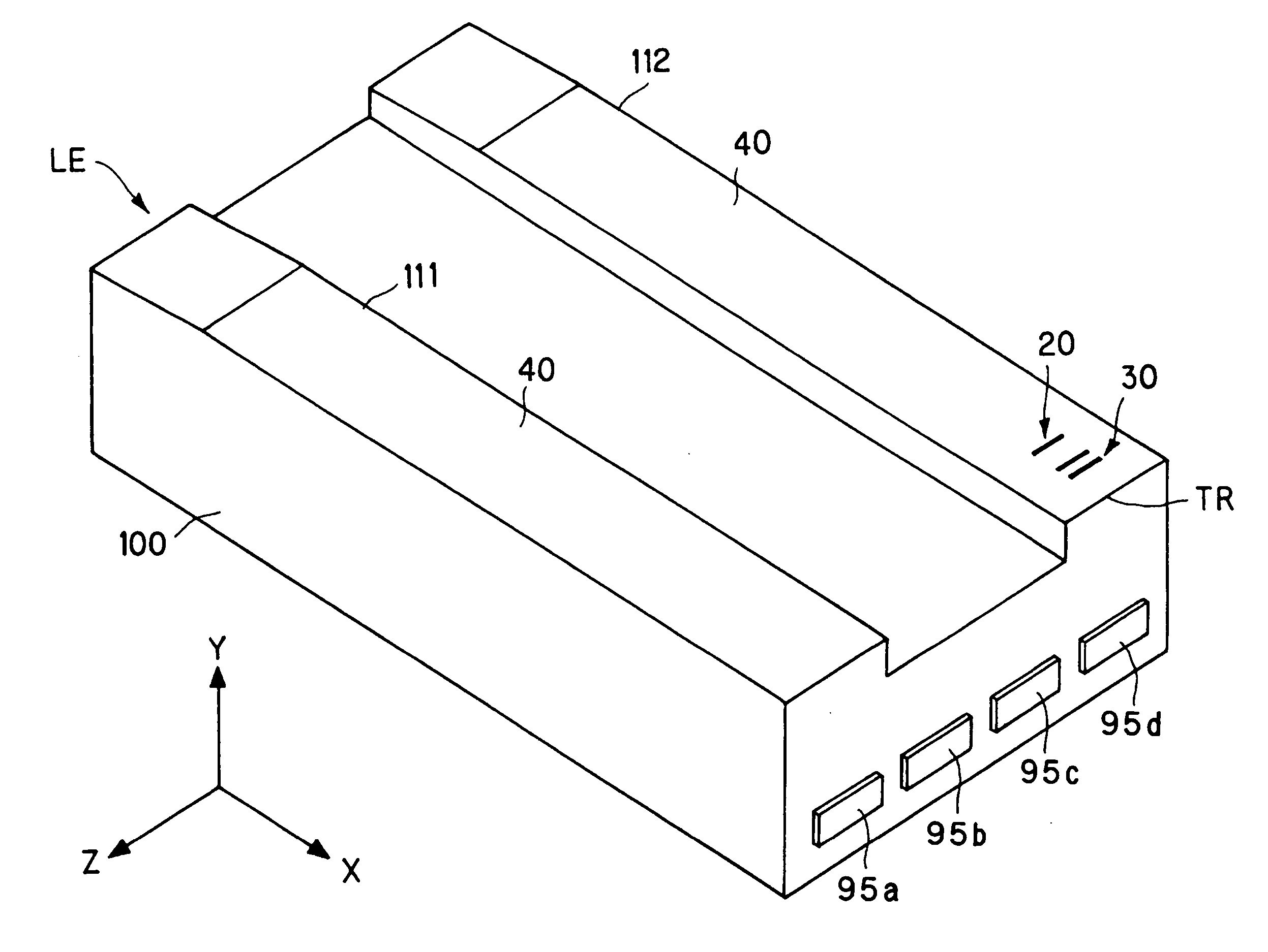
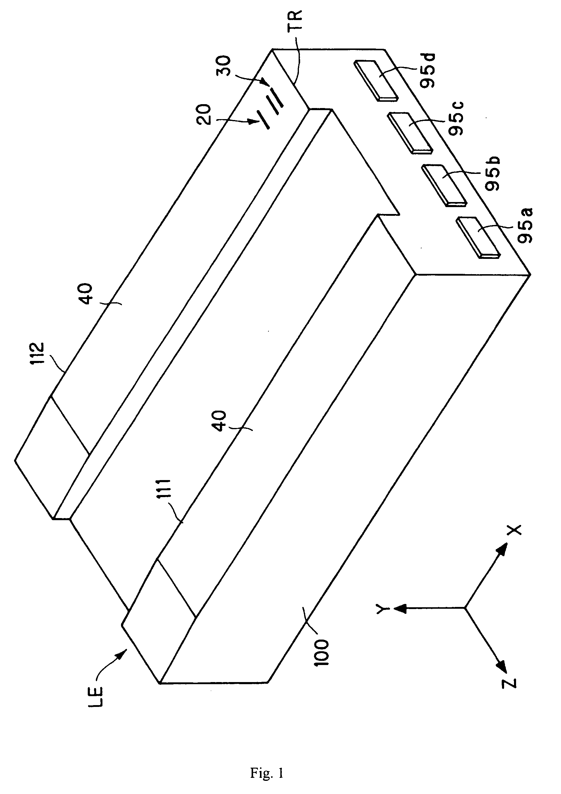
[0083] Performing the step S1-S3 shown in FIG. 5 step by step and cutting the wafer with compound read / write elements incorporated therein into a plurality of slices with a predetermined size, and forming a plurality of sample row bars (similar to the row bars 116 shown in FIG. 6b, i.e. a plurality of bars with a same structure) by such as a diamond cutter.

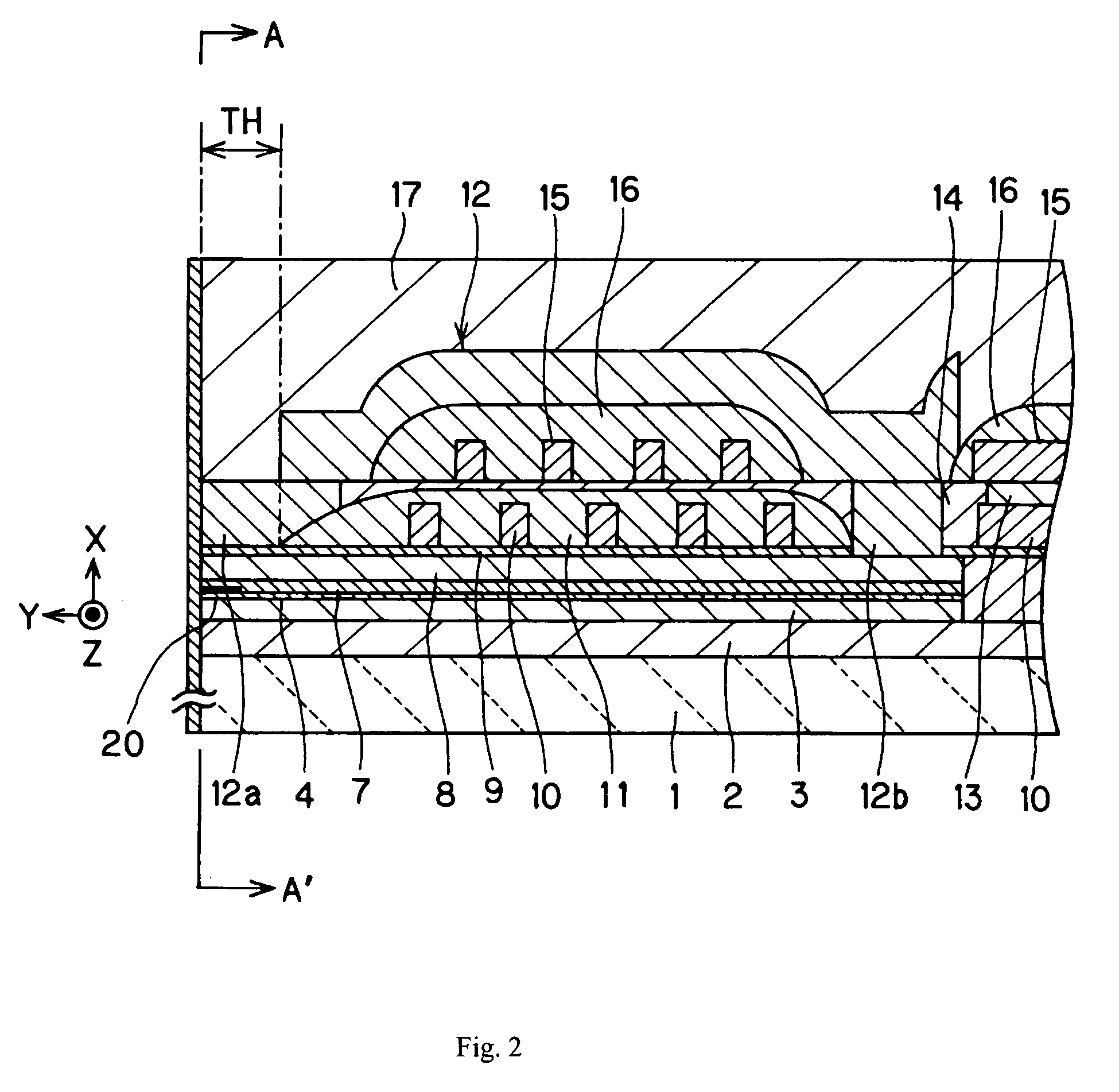
[0084] The sample row bar has a multi-filmed configuration as shown in FIGS. 2-4, which comprises an AlTiC base plate acting as the wafer of the substrate 1, an aluminum layer with a thickness of 5 μm functioning as the undercoat 2, a permalloy layer with a thickness of 2 μm serving as the bottom magnetic-shielding layer 3, a Ta layer with a thickness of 0.05 μm used as the first covering layer 4, a GMR element 20 (a more detailed illustration will be given later), a Ta layer with a thickness of 0.05 μm used as the second covering layer 7, a permalloy layer with a thickness of 4 μm as the top magnetic-shielding layer 8, and a NiFe


PUM


Abstract

A slider of the invention includes a substrate, a head element formed on the substrate and a protecting film formed on at least one portion of one surface of the substrate facing a magnetic recording medium. The protecting film comprises a base film, first DLC (diamond like carbon) film adjacent the substrate and a second DLC film. The carbon film density of said first DLC film is less than 3.1 (g/cm3) and the carbon film density of said second DLC film is more than 3.1 (g/cm3).

Description


Claims


Application Information

Patent Timeline
Owner SAE MAGNETICS (HK) LTD
Why Eureka
Try Eureka