Method for uniformly and controllably coating conducting carbon layer at surface of LiFePO4 granule surface
A conductive carbon and particle surface technology, applied in the direction of circuits, coatings, electrical components, etc., can solve the problems of inability to achieve uniform coating, large capacity loss, etc., and achieve the effect of increased conductivity and uniform thickness
- Summary
- Abstract
- Description
- Claims
- Application Information
AI Technical Summary
Problems solved by technology
Method used
Image

Examples
Embodiment 1
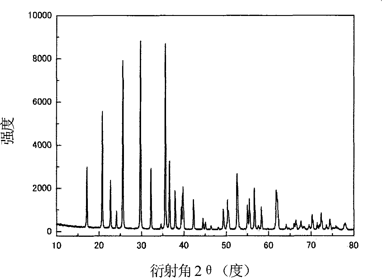
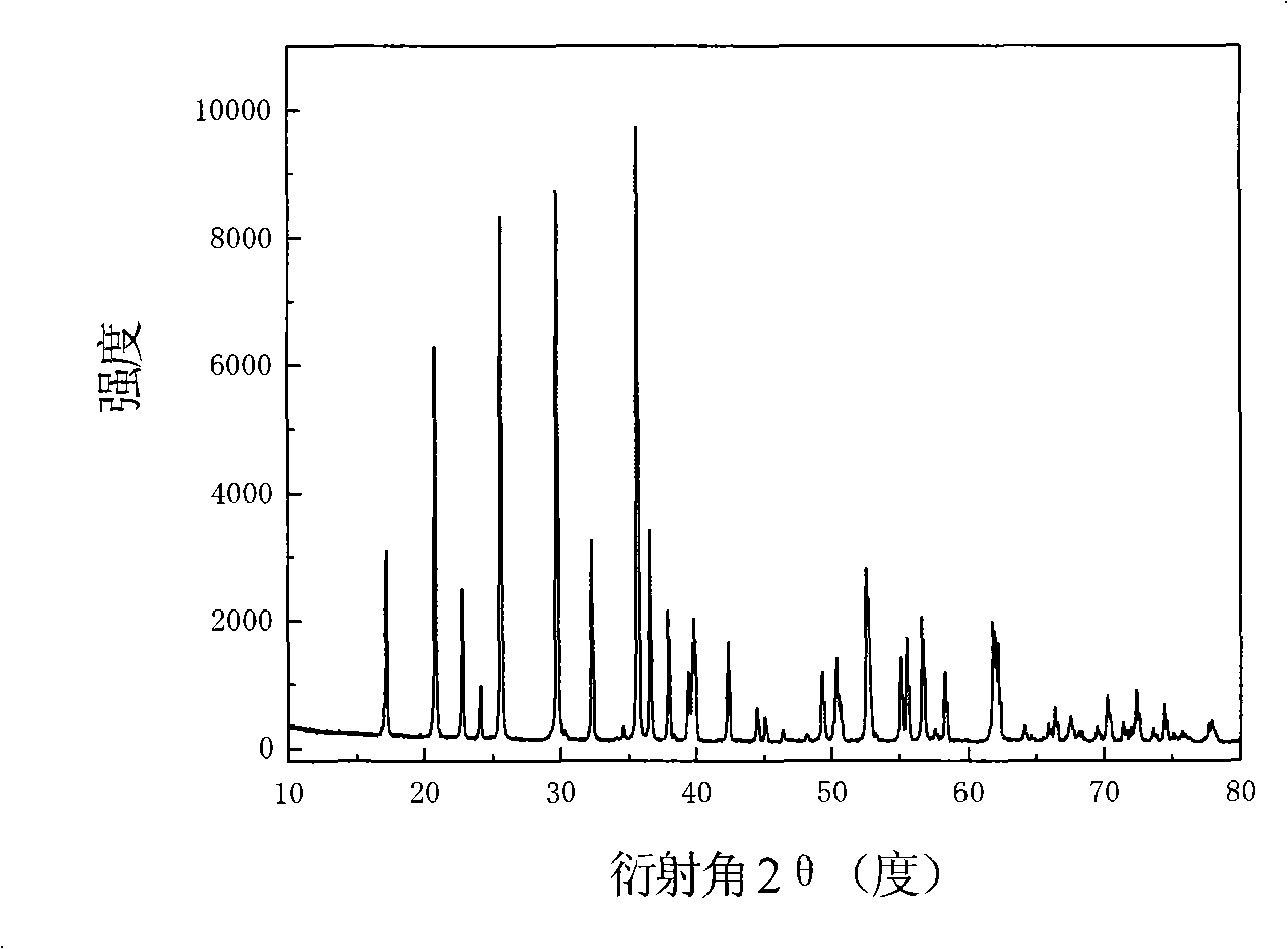
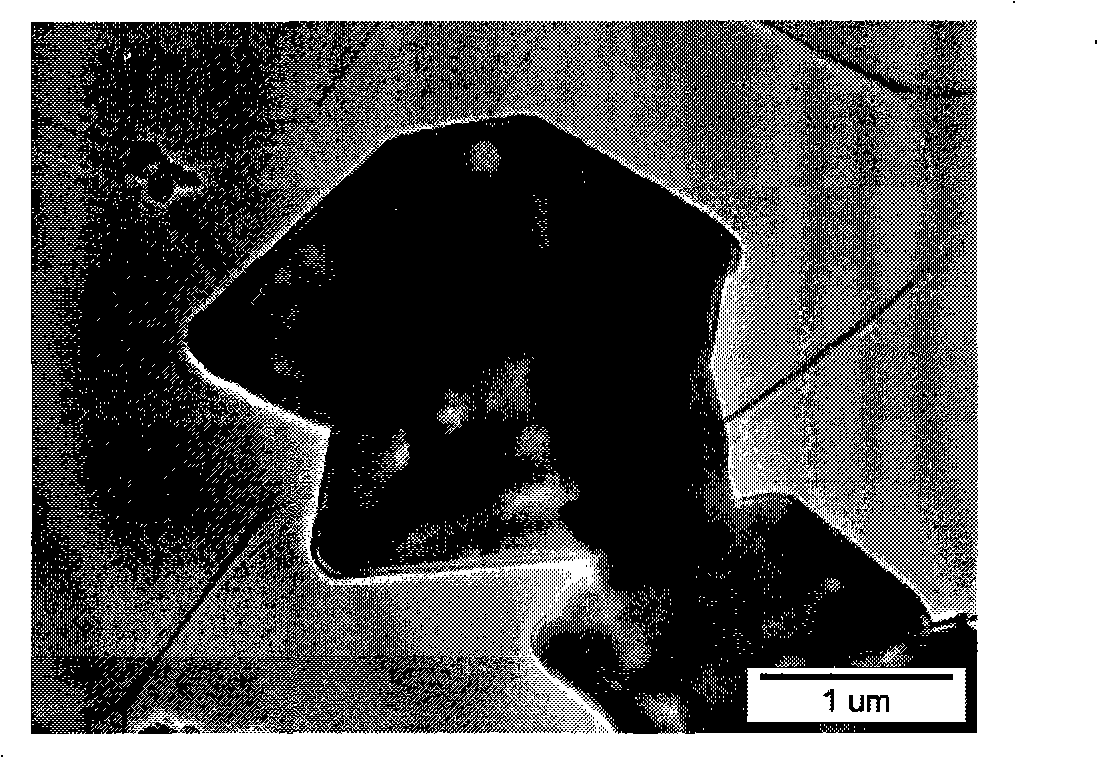
[0026] LiFePO 4 The powder is placed in the constant temperature zone of the chemical vapor deposition furnace, and then evacuated for 1 hour (the vacuum degree reaches about 10Pa), after the air in the furnace is exhausted, nitrogen gas is introduced, and after the temperature is raised to 720°C, acetylene gas is introduced for chemical vapor phase deposition. In the gas in the furnace, the volume percentage of acetylene gas is 20%, and the deposition time is 2 hours. The sample after carbon deposition was cooled to room temperature with the furnace, and then taken out. Carried out X-ray diffraction analysis to the sample of depositing carbon, and the sample before depositing ( Figure 1a ) comparison found that LiFePO 4 The structure of was not changed after carbon deposition ( Figure 1b ). The observation results of the transmission electron microscope showed that the thickness of the deposited carbon layer was very uniform ( Figure 2a ), the thickness of the carbon la
Embodiment 2
[0028] The difference from Example 1 is:
[0029] LiFePO 4 The powder is placed in the constant temperature zone of the chemical vapor deposition furnace, and then evacuated for 1 hour (the vacuum degree reaches about 10Pa), after the air in the furnace is exhausted, nitrogen gas is introduced, and after the temperature is raised to 700°C, acetylene gas is introduced for chemical vapor phase deposition. In the gas in the furnace, the volume percentage of acetylene gas is 5%, and the deposition time is 2 hours. The observation result of transmission electron microscope shows that the thickness of the deposited carbon layer is about 5 nanometers, and the thickness is very uniform ( Figure 4 ). The apparent conductivity of the sample after carbon deposition is 1.04Ω -1 m -1 .
Embodiment 3
[0031] The difference from Example 1 is:
[0032] LiFePO 4 The powder is placed in the constant temperature zone of the chemical vapor deposition furnace, and then purged with argon for 2 hours, and after the temperature is raised to 700°C, acetylene gas is introduced for chemical vapor deposition. In the gas in the furnace, the volume percentage of acetylene gas is 20%, and the deposition time is 0.5 hours. The observation result of transmission electron microscope shows that the thickness of the deposited carbon layer is about 8 nanometers, and the thickness is very uniform ( Figure 5 ). The apparent conductivity of the sample after carbon deposition is 1.29×10 -1 Ω -1 m -1 .
PUM
| Property | Measurement | Unit |
|---|---|---|
| Thickness | aaaaa | aaaaa |
| Thickness | aaaaa | aaaaa |
Abstract
Description
Claims
Application Information
 - R&D Engineer
- R&D Manager
- IP Professional
- Industry Leading Data Capabilities
- Powerful AI technology
- Patent DNA Extraction
Browse by: Latest US Patents, China's latest patents, Technical Efficacy Thesaurus, Application Domain, Technology Topic.
© 2024 PatSnap. All rights reserved.Legal|Privacy policy|Modern Slavery Act Transparency Statement|Sitemap