Reactor design for reduced particulate generation

Active Publication Date: 2006-05-18
ASM INTERNATIONAL
View PDF68 Cites 26 Cited by
  • Summary
  • Abstract
  • Description
  • Claims
  • Application Information

AI Technical Summary

Benefits of technology

[0012] According to another aspect of the invention, a method of semiconductor processing is provided. The method comprises providing a reactor comprising a coolant enclosure. The enclosure comprises a channel and is

Problems solved by technology

Deposition results, however, can be adversely affected by the presence of particulate matter in the furnace.
In some cases, the p

Method used


Image

  • Reactor design for reduced particulate generation
  • Reactor design for reduced particulate generation
  • Reactor design for reduced particulate generation

Examples


Embodiment Construction

[0016] Co-pending and co-assigned U.S. patent application Ser. No. 11 / 096,861, filed Mar. 31, 2005, the entire disclosure of which is incorporated herein by reference, describes the deposition of titanium nitride films by flowing TiCl4 and NH3 as precursors into a furnace. Such a process has been found to be very sensitive to the occurrence of particles and can be prone to the formation of particles. For example, particles can result from the formation of reaction by-products, such as NH4Cl, that condense on relatively cool furnace surfaces. These particles can then settle on the substrates being processed and can degrade process results.

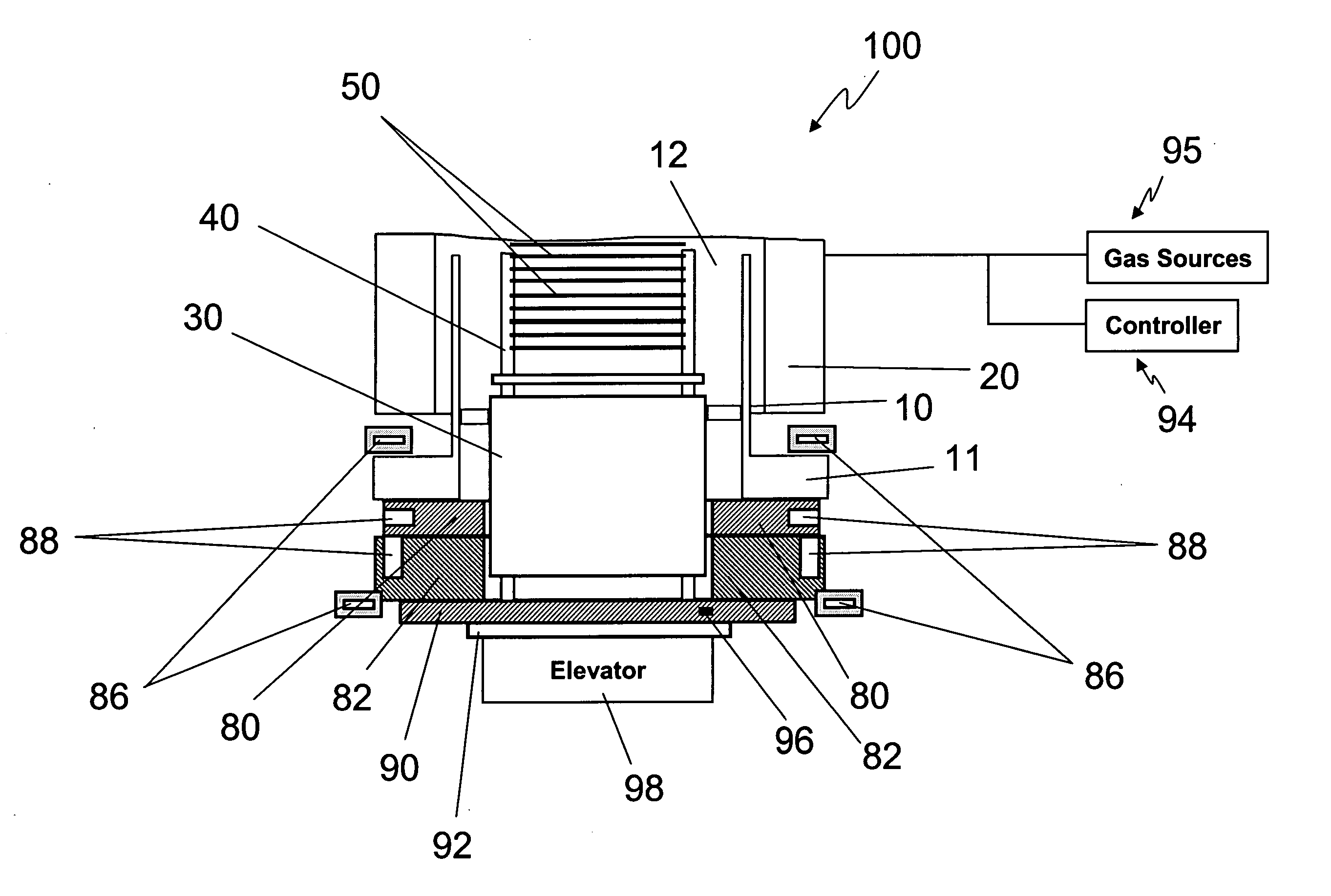
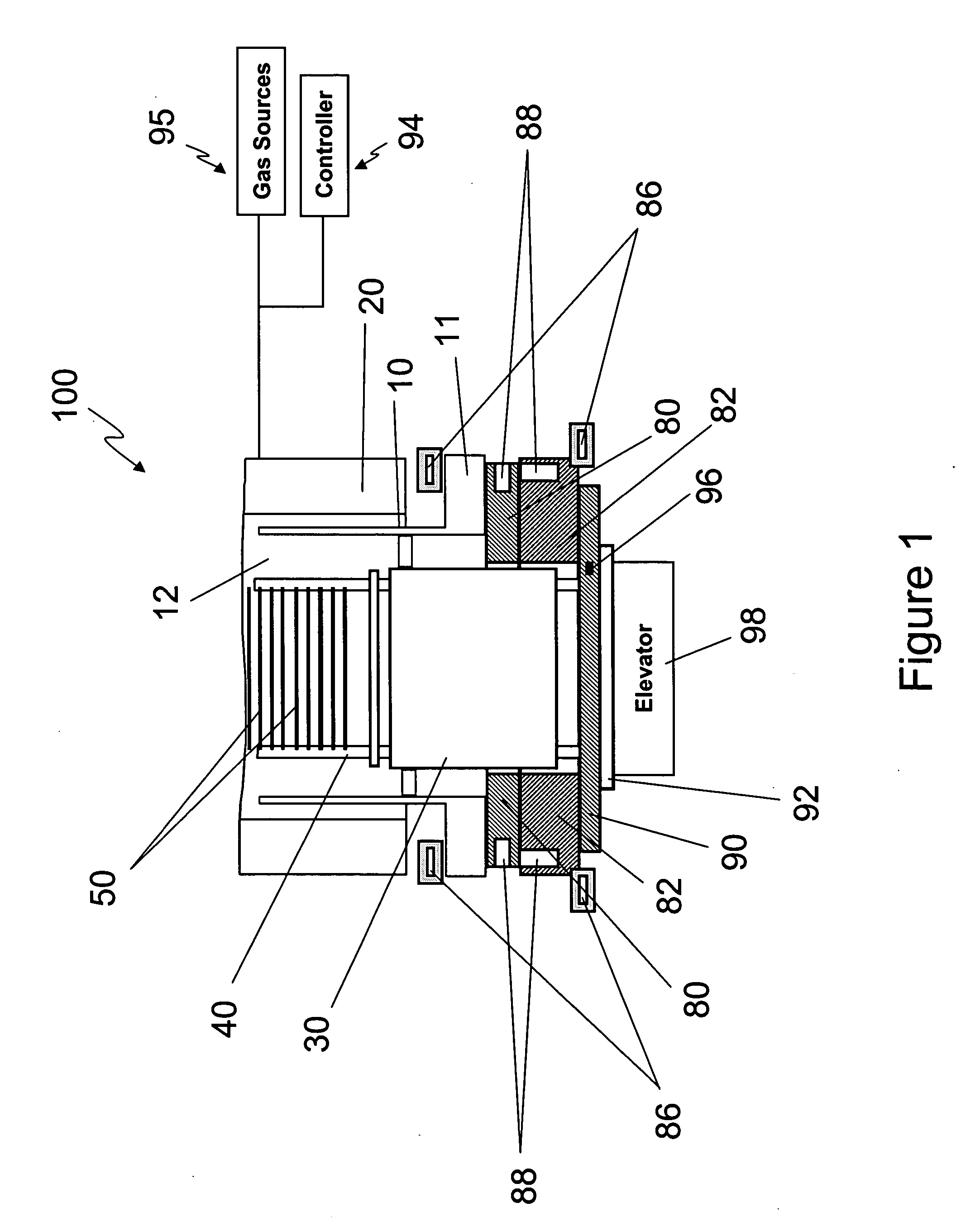
[0017] To minimize condensation and, thus, minimize particle formation, U.S. patent application Ser. No. 11 / 096,861 discloses maintaining the flange of the process tube in the vertical furnace at an elevated temperature. In the exemplary reactor discussed in that patent application, the process tube delimits a reaction chamber for accommodating an


PUM

PropertyMeasurementUnit
Temperatureaaaaaaaaaa

Abstract

Particle formation in semiconductor fabrication process chambers is reduced by preventing condensation on the door plates that seal off the process chambers. Particles can be formed in a process chamber when reactant gases condense on the relatively cool surfaces of a door plate. This particle formation is minimized by heating the door plate to a temperature high enough to prevent condensation before flowing reactant gases into the process chamber. The door plate can be heated using a heat source, e.g., a resistive heater, that is in direct contact with the door plate or the heat source can heat the door plate from a distance by radiative or inductive heating. In addition, the door plate can open to allow loading and unloading of a wafer load. As it passes flanges near the door plate, the wafer load can transfer heat to those flanges. To prevent overheating, the flange is provided with a coolant-containing channel having walls that are spaced from the flange by O-rings. The spacing of the channel walls to the flange can be varied to vary the amount of thermal contact and cooling achieved using the channels.

Description


Claims


Application Information

Patent Timeline
Owner ASM INTERNATIONAL
Why Eureka
Try Eureka