Angled cooling divider wall in blade attachment

Active Publication Date: 2006-11-23
PRATT & WHITNEY CANADA CORP
View PDF13 Cites 4 Cited by
  • Summary
  • Abstract
  • Description
  • Claims
  • Application Information

AI Technical Summary

Benefits of technology

[0004] It is therefore an object of the present invention to provide an impr

Problems solved by technology

Nevertheless, conventional divider walls or ribs have limited effect.
The centrifugal load generated by the high rotational speed of the rotor assembly re

Method used


Image

  • Angled cooling divider wall in blade attachment
  • Angled cooling divider wall in blade attachment
  • Angled cooling divider wall in blade attachment

Examples


Embodiment Construction

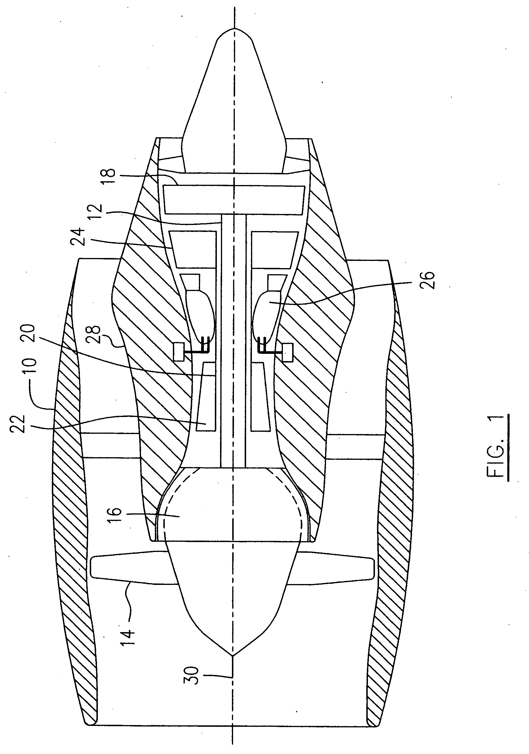
[0018] A turbofan engine illustrated schematically in FIG. 1, presented as an example of the application of the present invention, includes a housing or nacelle 10, a low pressure spool assembly seen generally at 12 which includes a fan 14, a low pressure compressor 16 and a low pressure turbine 18, a high pressure spool assembly seen generally at 20 which includes a high pressure compressor 22 and a high pressure turbine 24. A core casing 28 surrounds the low and high pressure spool assemblies 12 and 20 to define a main fluid path (not indicated) therethrough. In the main fluid path there is provide a combustor seen generally at 26 with fuel injecting means (not indicated) to constitute a gas generator section. The compressors 16 and 22 drive a main airflow (not indicated) along the main fluid path and provide bleed airflow as a cooling air source for cooling the combustor 26 as well as the turbines 18 and 24.

[0019] It should be noted that similar components of the different embodime


PUM


Abstract

A rotor blade of a gas turbine engine includes a blade root defining a cooling airflow entry cavity therein, in fluid communication with internal cooling air passages through the blade. The cavity includes opposed side walls and at least one divider wall extending therebetween. At least one end portion of the divider walls adjoins one of the side walls in an angled direction relative to a perpendicular direction of the side walls.

Description


Claims


Application Information

Patent Timeline
Owner PRATT & WHITNEY CANADA CORP
Why Eureka
Try Eureka