Disk Apparatus

a technology of disk apparatus and spherical disk, which is applied in the field of spherical disk apparatus, can solve the problems of limiting the thinning of the disk apparatus body and hindering the operation of the lever, and achieve the effects of smooth sliding, preventing the damage of the disk, and smooth sliding

Inactive Publication Date: 2007-12-27
PANASONIC CORP
View PDF2 Cites 9 Cited by
  • Summary
  • Abstract
  • Description
  • Claims
  • Application Information

AI Technical Summary

Benefits of technology

The invention relates to an improved design for protecting disks used with magnetic recording devices such as hard discs or CD players. This improves their durability against damage caused during use without compromising data storage capabilities.

Problems solved by technology

The technical problem addressed in this patented technology relates to improving the design of a compact disc drive system without increasing its overall dimensions when transferring data from one device to other devices with different sizes. This requires a certain minimum space around the rotating part called a gutter where the disk may move during rotation.

Method used


Image

  • Disk Apparatus
  • Disk Apparatus
  • Disk Apparatus

Examples


Embodiment Construction

[0053] A disk apparatus according to an embodiment of the present invention will be explained.

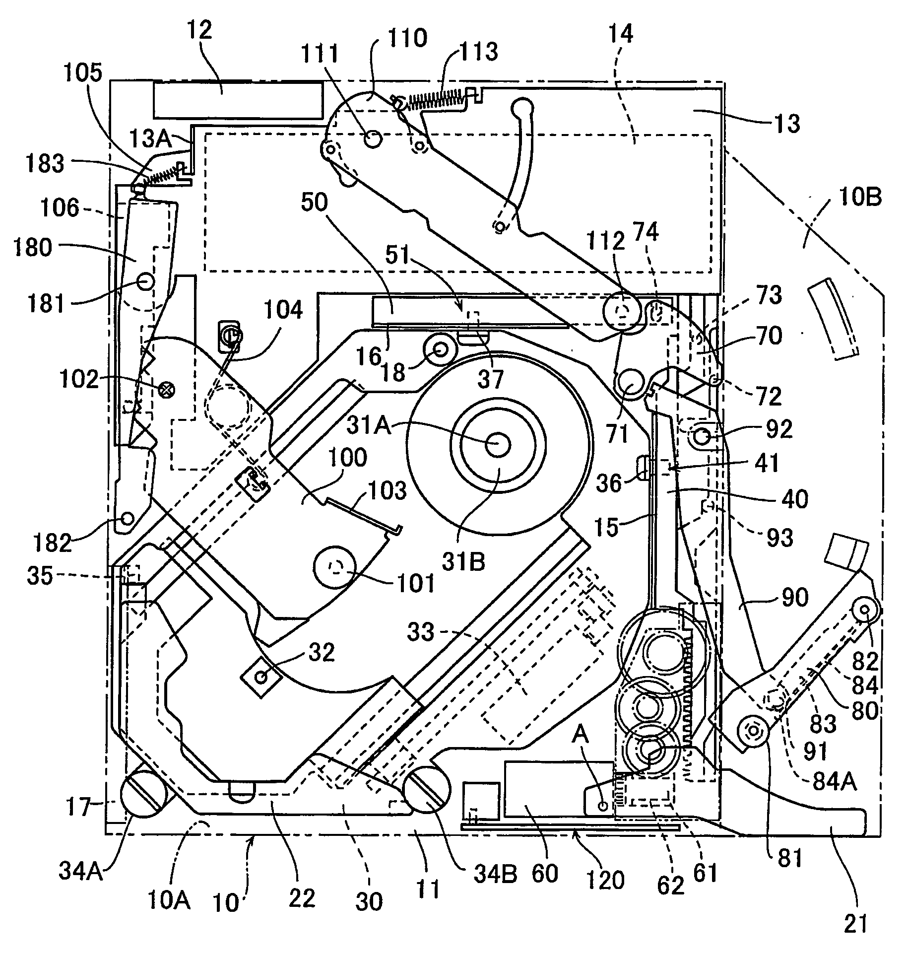
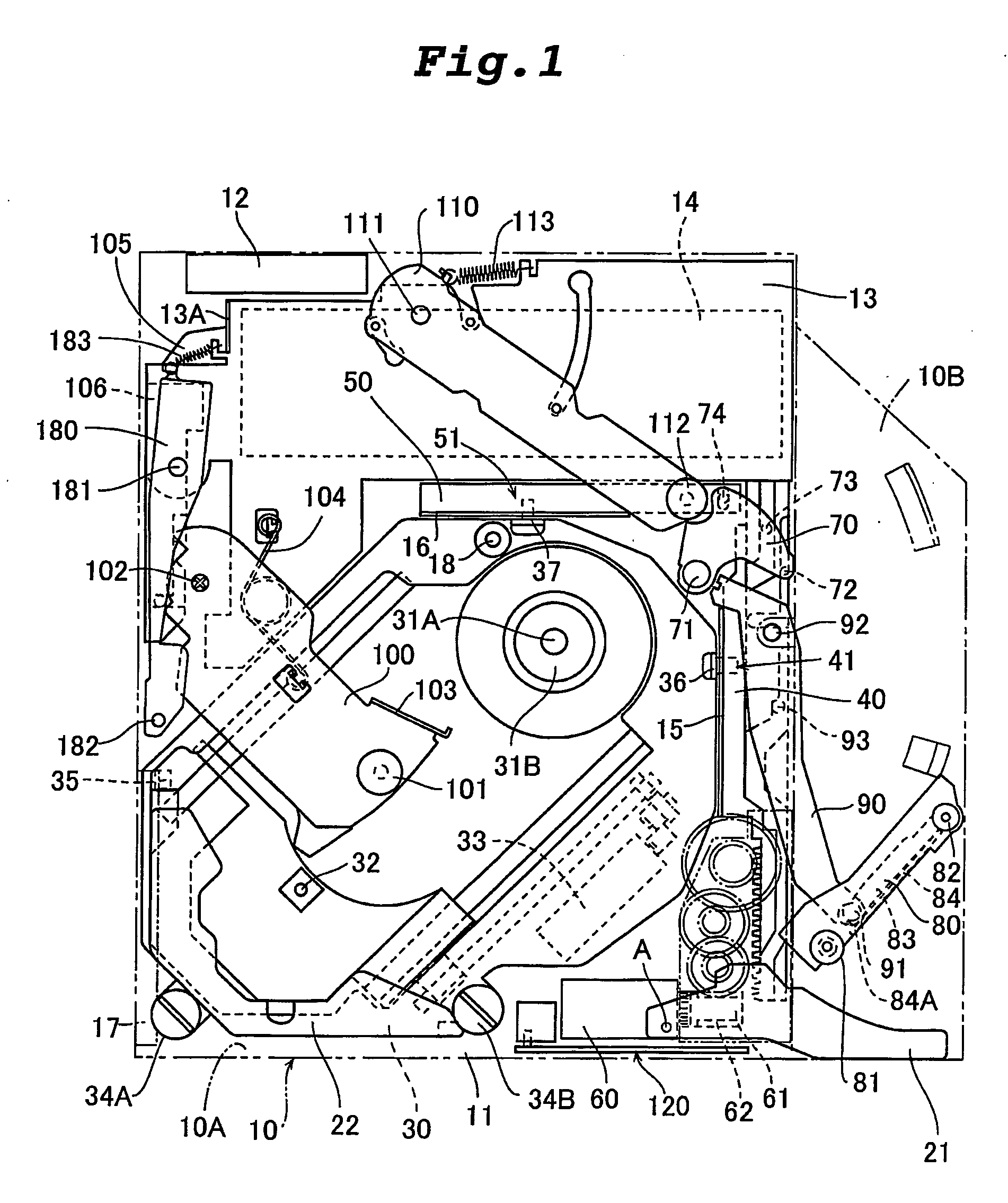
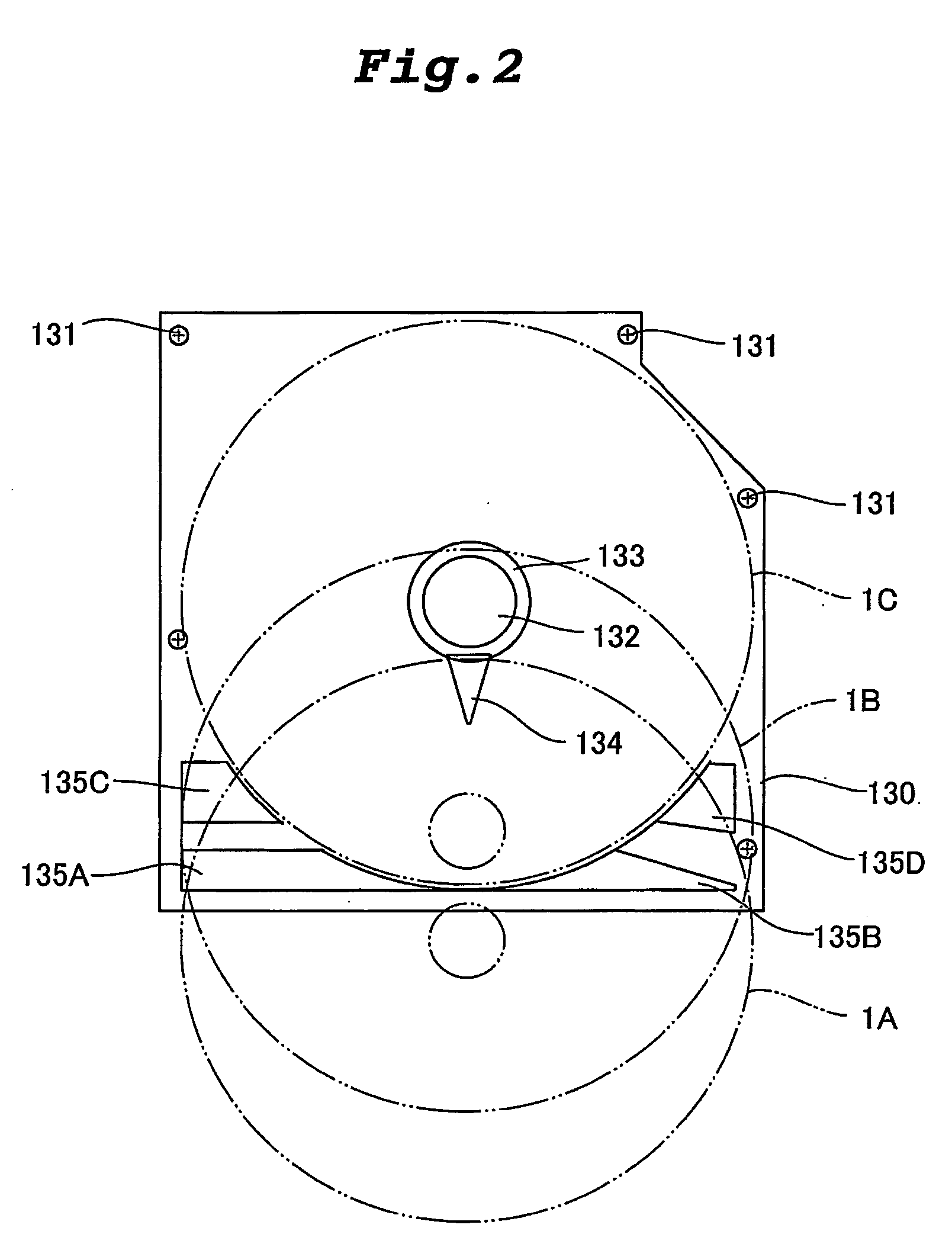
[0054]FIG. 1 is a plan view of a base body of a disk apparatus according to an embodiment of the present invention. FIG. 2 is a plan view of a lid of the disk apparatus. FIG. 3 is a front view of a bezel mounted on a front surface of a chassis outer sheath of the disk apparatus. FIG. 4 is an enlarged sectional view of an essential portion of a guide of a discharge lever of the disk apparatus.

[0055] The disk apparatus of the embodiment comprises a chassis outer sheath having a base body and a lid. A bezel is mounted on a front surface of the chassis outer sheath. The disk apparatus of the embodiment is of a slot-in type in which a disk is directly inserted into the disk apparatus from a disk inserting opening formed in the bezel shown in FIG. 3.

[0056] As shown in FIG. 1, various parts having function for recording or replaying into or from a disk, and a function for loading the disk are moun


PUM


Abstract

A disk apparatus comprising a chassis outer sheath having a base body 10 and a lid, in which a front surface of the chassis outer sheath is formed with a disk inserting opening 11 into which a disk is directly inserted, a lever which is operated when the disk is inserted or discharged is provided in the chassis outer sheath, the lever is provided at its movable side end with a guide 17, and the disk is guided by the guide 17, wherein
the guide 17 comprises a stationary portion 101B fixed to the lever, a movable portion 101C which is displaced with respect to the stationary portion 101B, and an elastic body which biases the movable portion 101C in a direction away from the stationary portion 101B.

Description


Claims


Application Information

Patent Timeline
Owner PANASONIC CORP
Why Eureka
Try Eureka