Polyethylene plastic submerged material impurity removing system

A polyethylene plastic and impurity removal technology, applied in the field of polyethylene processing, can solve problems such as affecting the effect and difficult to remove

Inactive Publication Date: 2020-05-08
刘林杰
View PDF5 Cites 0 Cited by
  • Summary
  • Abstract
  • Description
  • Claims
  • Application Information

AI Technical Summary

Problems solved by technology

[0004] 1. When a large amount of sheet-like polyethylene is crushed, the internal rolling friction will generate static electricity, so that the fluff in the air will adhere to the surface of the polyethylene. In the subsequent pool, it is difficult to dislodge the fluff because the fluff is too small. The two are disengaged, affecting the effect of subsequent regeneration
[0005] 2. When the lint is partly separated by the pool and floats on the surface of the pool, in the process of taking out the polyethylene, it will be attached to the lint on the water surface again, and it will be difficult to remove later

Method used


Image

  • Polyethylene plastic submerged material impurity removing system
  • Polyethylene plastic submerged material impurity removing system
  • Polyethylene plastic submerged material impurity removing system

Examples


Embodiment 1

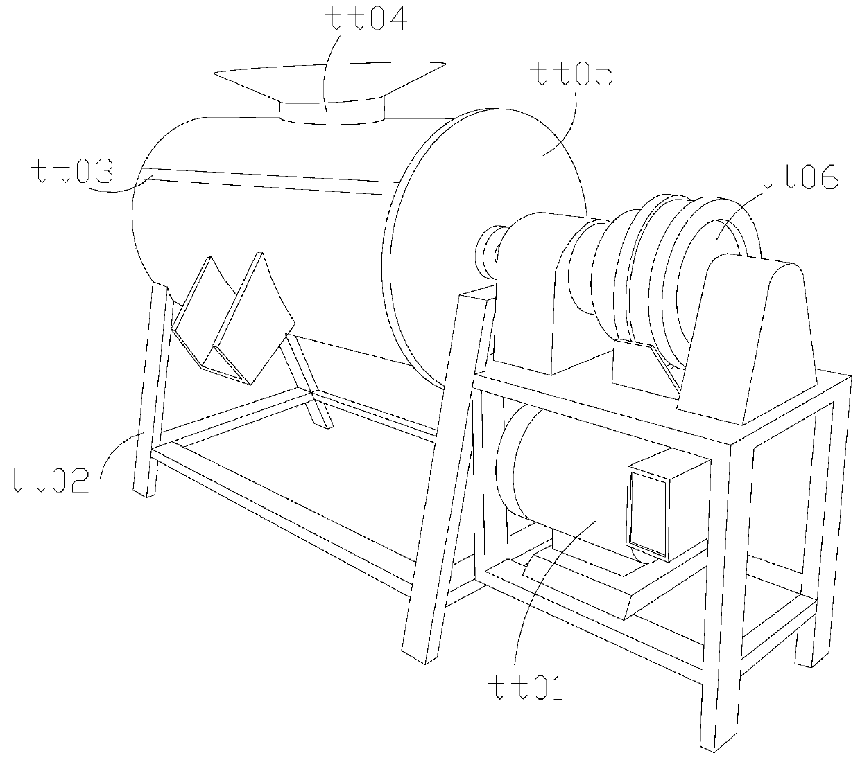
[0032] as attached figure 1 to attach Figure 5 Shown:

[0033] The invention provides a polyethylene plastic submerged material impurity removal system, the structure of which includes a main control machine tt01, a support leg tt02, a support filter layer tt03, an inlet tt04, a side guard plate tt05, and a main control wheel tt06.

[0034] The main control unit tt01 is connected to the main control wheel tt06 through wires, the support leg tt02 is welded to the lower surface of the filter layer tt03, the filter layer tt03 is connected with the insertion port tt04, and the main control wheel tt06 runs through the Inside the side guard tt05.

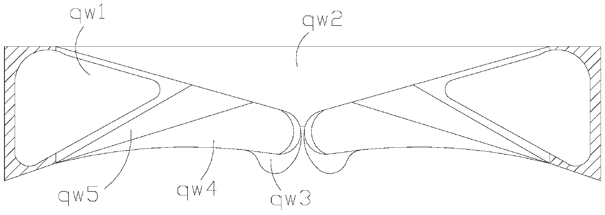
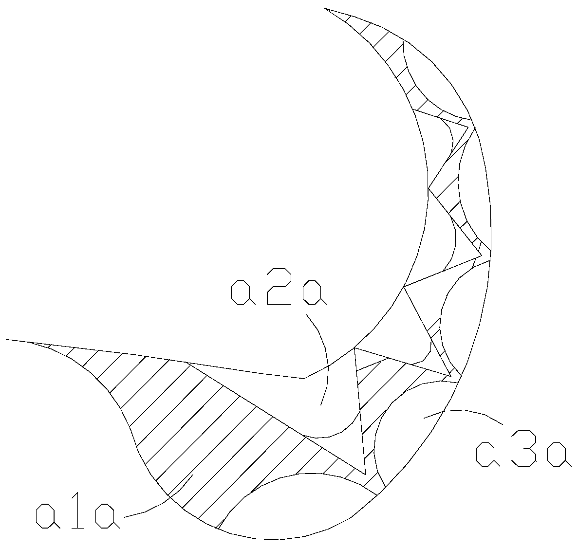
[0035] Wherein, the inlet tt04 includes a solid force angle qw1, an inclined opening qw2, a sticking head qw3, a pressure-assisting edge qw4, and an angle expansion core qw5. The solid force angle qw1 is connected with the angle expansion core qw5. The end of the corner core qw5 away from the solid angle qw1 is connected to the pressu...

Embodiment 2

[0040] as attached Figure 6 to attach Figure 8 Shown:

[0041]Wherein, the support filter layer tt03 includes an inlet ee1, an outer limit shell ee2, an extrusion bar ee3, and a grid ee4, the inlet ee1 runs through the inside of the outer limit shell ee2, and the grid ee4 is embedded in the outer limit shell Inside ee2, the intrusion bar ee3 is connected with the outer limit shell ee2, the intrusion bar ee3 is evenly distributed in the horizontal direction, the outer limit shell ee2 is in a circular structure, and the introduction port ee1 limits the movement of foreign objects. The range of the inlet is large, and the strip ee3 is squeezed in to separate the water from the fluff.

[0042] Wherein, the intrusion bar ee3 includes a beam opening xx01, a pocket grid xx02, an outer limit ring xx03, and a one-way angle xx04, and the one-way angle xx04 is connected with the beam opening xx01, and the one-way angle xx04 is embedded in the outer limit Inside the ring xx03, the po...


PUM


Abstract

The invention discloses a polyethylene plastic submerged material impurity removing system. The polyethylene plastic submerged material impurity removing system structurally comprises a main control computer, supporting legs, a supporting filter layer and an imbedding opening, wherein the main control computer is connected with a main control wheel through a wire, the supporting legs are welded tothe lower surface of the supporting filter layer, objects are extruded into an adhesive supporting head, can be adhered by an adhesive head at first, the extrusion force stacked at the rear end enables the objects to be continuously extruded, the rear end of the object is buffered and dragged by an adhesive tape, and is changed according to the moving direction of an object, so that the object can be smoothly extruded into the interior through adhesion of the adhesive supporting head, the surface of the object can be adsorbed when the object is guided into machining equipment, batting of theobject can be separated, water is placed in the interior, the residual batting can be separated from the object through impulsive force of the water and can smoothly slide into bag grids to be placedso that the foreign object can smoothly slide, the rear end of a position expanding strip is uniformly stressed by uniform force balls, the batting further left on the surface of the object and is separated through the water when the submerged material is separated, and the batting can be intercepted for storage.

Description

technical field [0001] The invention belongs to the field of polyethylene processing, and more specifically relates to a system for removing impurities from polyethylene plastic submerged materials. Background technique [0002] Before the flaky polyethylene needs to be recycled, it needs to be crushed to make it into flaky pieces of similar size, so that the submerged material can be separated through the pool, and the subsequent regeneration process can be performed on it. [0003] Based on the above-mentioned inventor's discovery, the existing polyethylene plastic impurity removal system mainly has the following deficiencies, such as: [0004] 1. When a large amount of sheet-like polyethylene is crushed, the internal rolling friction will generate static electricity, so that the fluff in the air will adhere to the surface of the polyethylene. In the subsequent pool, it is difficult to dislodge the fluff because the fluff is too small. The two are disengaged, affecting th...

Claims


Application Information

Patent Timeline
IPC IPC(8): B29B17/02B03B11/00
CPCB03B11/00B29B17/02B29B2017/0244Y02W30/62
Inventor 刘林杰
Owner 刘林杰
Why Eureka
Try Eureka