Travel Control Method For Self-Propelled Carriage

Inactive Publication Date: 2008-05-15
HONDA MOTOR CO LTD
View PDF22 Cites 1 Cited by
  • Summary
  • Abstract
  • Description
  • Claims
  • Application Information

AI Technical Summary

Benefits of technology

[0015]According to the thus-arranged control method, the large-scale lateral wobbling and vibration that has conventionally occurred in a self-propelled carriage can be dramatically reduced. Therefore, precision parts and other parts adversely affected by vibration can be transported.

Problems solved by technology

Therefore, precision parts and other parts adversely affected by vibration can be transported.

Method used


Image

  • Travel Control Method For Self-Propelled Carriage
  • Travel Control Method For Self-Propelled Carriage
  • Travel Control Method For Self-Propelled Carriage

Examples


Example

[0023]The embodiments of the present invention are now described below with reference to the accompanying drawings.

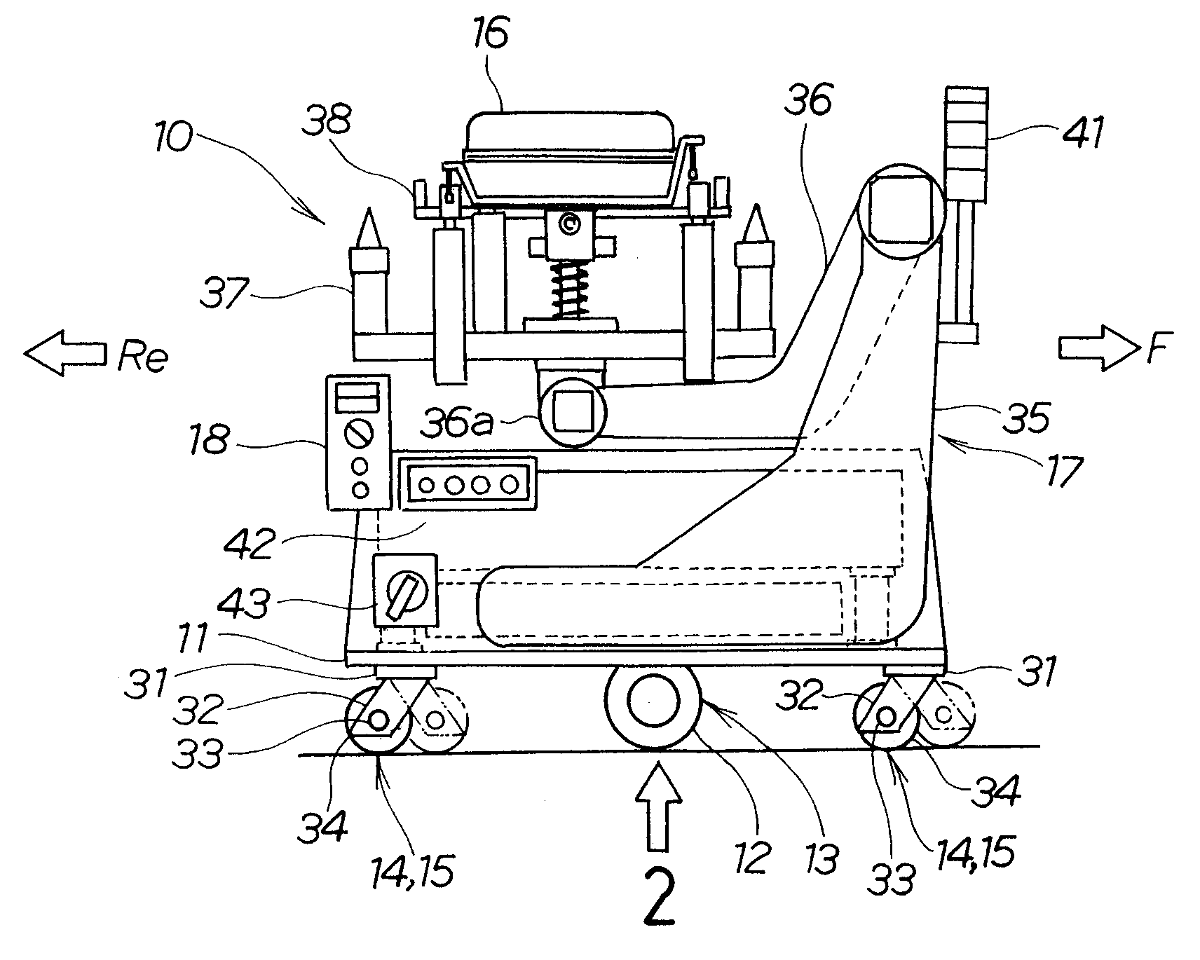
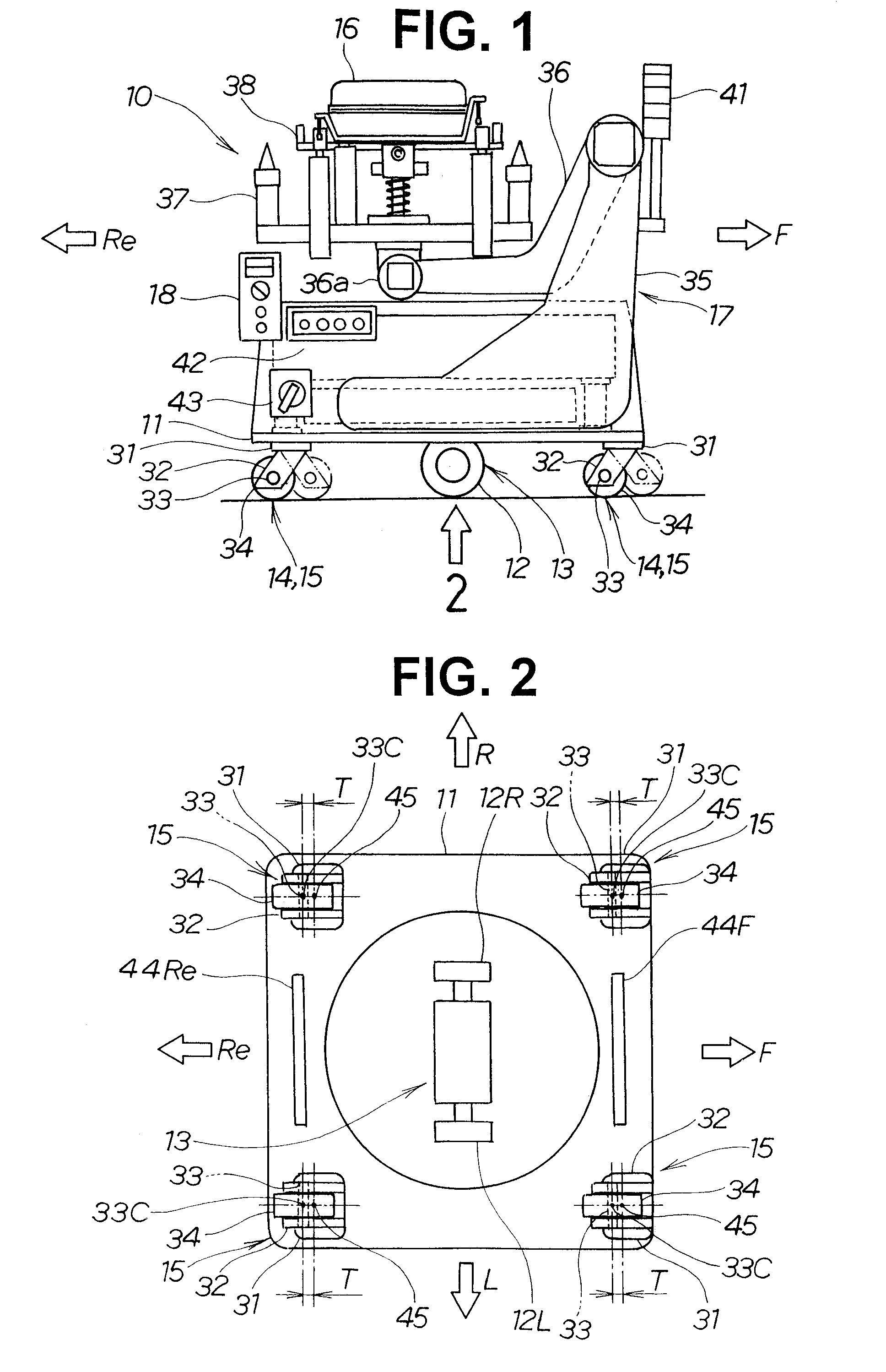
[0024]In FIGS. 1 and 2, a carriage is oriented so that F is a forward direction, Re is a backward direction, R is a rightward direction, and L is a leftward direction; and a carriage 10 is assumed to be in forward movement when working in the forward direction, and in backward movement when working in the backward direction.

[0025]FIG. 1 is a side view of a self-propelled carriage according to the present invention, comprising a caster wheel. The main elements constituting the self-propelled carriage 10 are a platform 11 that doubles as a frame for the carriage; a drive section 13 for driving the carriage 10, with the drive section 13 provided with a drive wheel 12, and mounted to a lower surface of the platform 11; and a caster wheel 15 for supporting the carriage 10, with the caster wheel 15 mounted as a reinforcing wheel 14 to a front and rear of the drive section 13.

[00


PUM


Abstract

A travel control method for a self-propelled carriage having a travel control section for controlling steering-driving wheels. In the method, the steering-driving wheels are steered by a predetermined angle based on a direction change command, and in this state, the carriage is moved forward and backward for a predetermined distance to make the carriage depart from a base line. Then, the carriage is steered toward the base line to return to the base line. After that, the carriage is made to be able to travel along the base line.

Description


Claims


Application Information

Patent Timeline
Owner HONDA MOTOR CO LTD
Why Eureka
Try Eureka