Methods of Manufacturing Non-Volatile Memory Devices Including Charge-Trapping Layers

a non-volatile memory and charge-trapping layer technology, applied in semiconductor devices, medical science, surgery, etc., can solve the problems of deteriorating high-temperature stress (hts) characteristics of non-volatile memory devices, slow i/o speed, data loss of volatile semiconductor memory devices, etc., and achieve the effect of increasing the etching ra

Inactive Publication Date: 2008-08-07
SAMSUNG ELECTRONICS CO LTD
View PDF3 Cites 4 Cited by
  • Summary
  • Abstract
  • Description
  • Claims
  • Application Information

AI Technical Summary

Benefits of technology

The technical effect of this patented method involves creating a charged trapped layer on top of another material called water or other solvents during manufacturing processes for semiconductor devices such as solar cells by exposure them with these materials at high temperatures. This process helps increase their efficiency while also prevent damage from moist environments like rainwater.

Problems solved by technology

This patented technical problem addressed by this patents relates to improving performance of electronic memories used with low energy consumption rates due to their ability to store large amounts of data without losing it over time during periods where they were turned OFF. Existing solutions involve utilizing special materials that can improve these properties but also increase costs associated with manufacturing them.

Method used


Image

  • Methods of Manufacturing Non-Volatile Memory Devices Including Charge-Trapping Layers
  • Methods of Manufacturing Non-Volatile Memory Devices Including Charge-Trapping Layers
  • Methods of Manufacturing Non-Volatile Memory Devices Including Charge-Trapping Layers

Examples


Embodiment Construction

[0030]Embodiments of the invention now will be described more fully hereinafter with reference to the accompanying drawings, in which embodiments of the invention are shown. This invention may, however, be embodied in many different forms and should not be construed as limited to the embodiments set forth herein. Rather, these embodiments are provided so that this disclosure will be thorough and complete, and will fully convey the scope of the invention to those skilled in the art. Like reference numerals refer to like elements throughout.

[0031]It will be understood that when an element is referred to as being “on” another element, it can be directly on the other element or intervening elements may be present. In contrast, when an element is referred to as being “directly on” another element, there are no intervening elements present. As used herein, the term “and / or” includes any and all combinations of one or more of the associated listed items.

[0032]It will be understood that, alt


PUM


Abstract

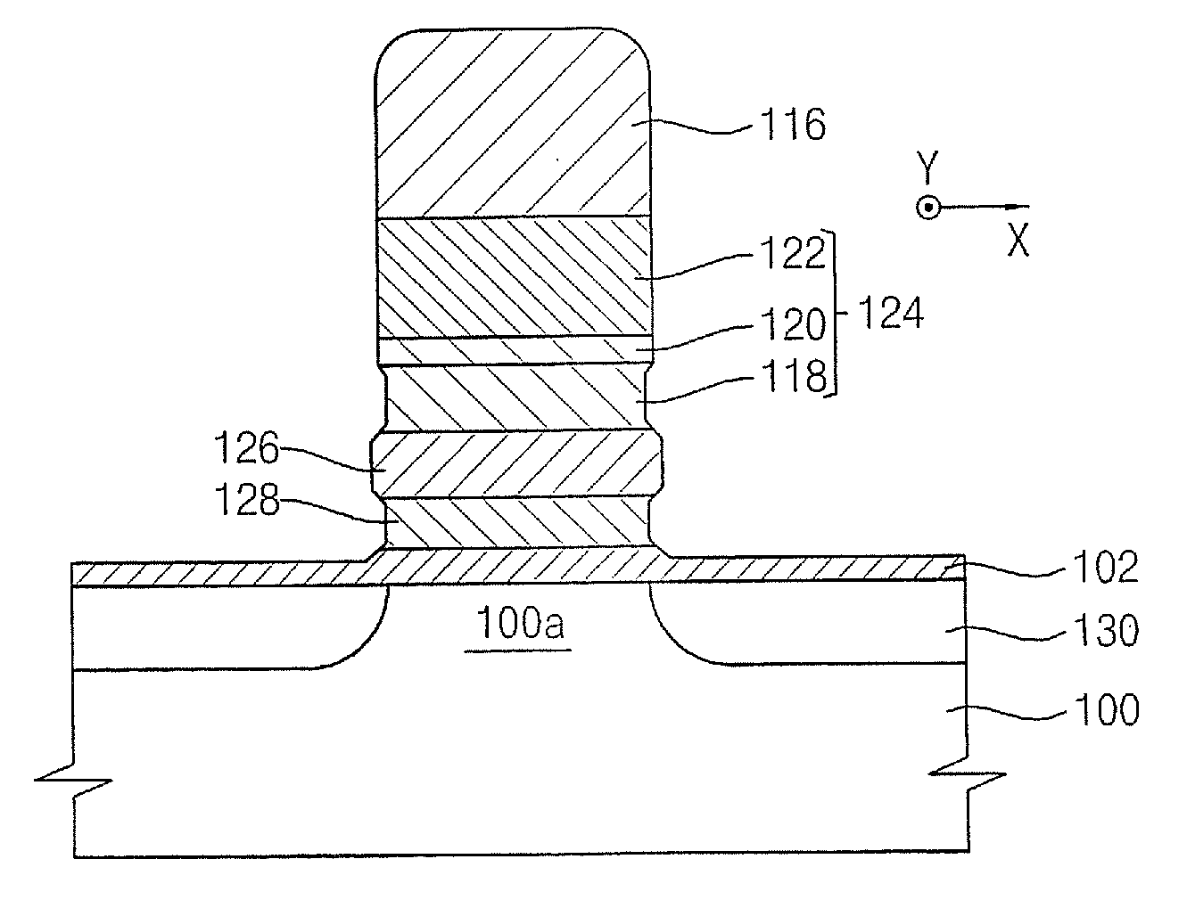
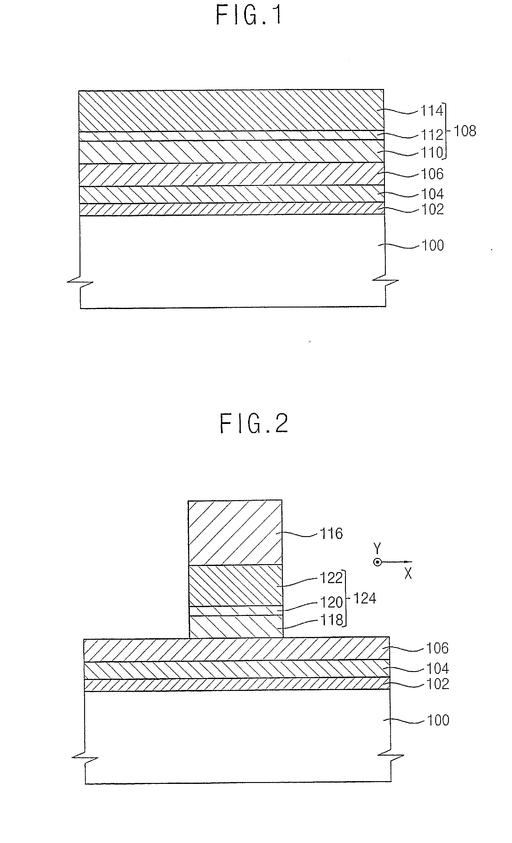
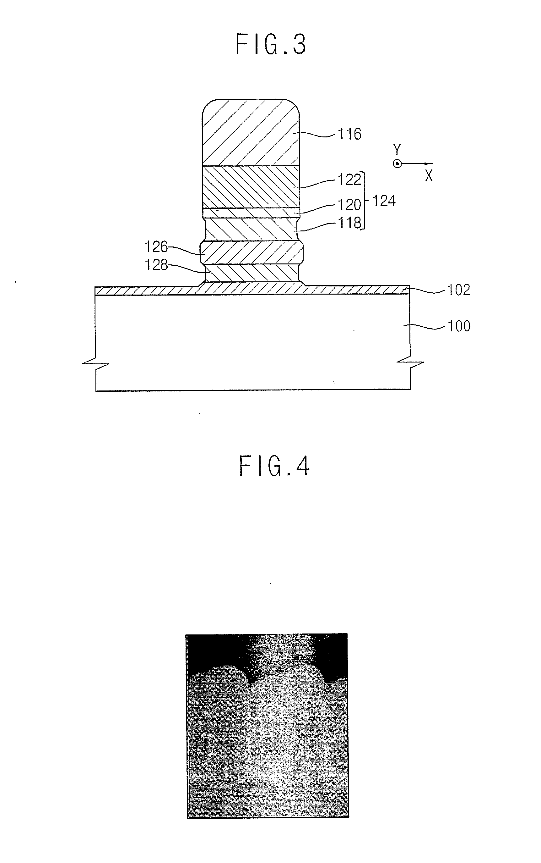
Methods of manufacturing non-volatile memory devices are provided including sequentially forming a tunnel insulating layer, a charge-trapping layer, a blocking layer and a conductive layer on a substrate having a channel region. The conductive layer is patterned to form a word line structure, and the blocking layer and the charge-trapping layer are etched using an aqueous acid solution as an etching solution to form a blocking layer pattern and a charge-trapping layer pattern.

Description


Claims


Application Information

Patent Timeline
Owner SAMSUNG ELECTRONICS CO LTD
Why Eureka
Try Eureka