Mode strut and divergent flap interface

Inactive Publication Date: 2008-09-25
RAYTHEON TECH CORP
View PDF17 Cites 5 Cited by
  • Summary
  • Abstract
  • Description
  • Claims
  • Application Information

AI Technical Summary

Benefits of technology

[0005]In one example, a gas turbine engine includes an exhaust nozzle. The exhaust nozzle includes a flap supported relative to a static structure by a strut. The flap includes a backbone providing a slot. A slider interconnects a strut end to the backbone. In one example, the sli

Problems solved by technology

This has resulted in wear and galling between the boss and strut end,

Method used


Image

  • Mode strut and divergent flap interface
  • Mode strut and divergent flap interface
  • Mode strut and divergent flap interface

Examples


Embodiment Construction

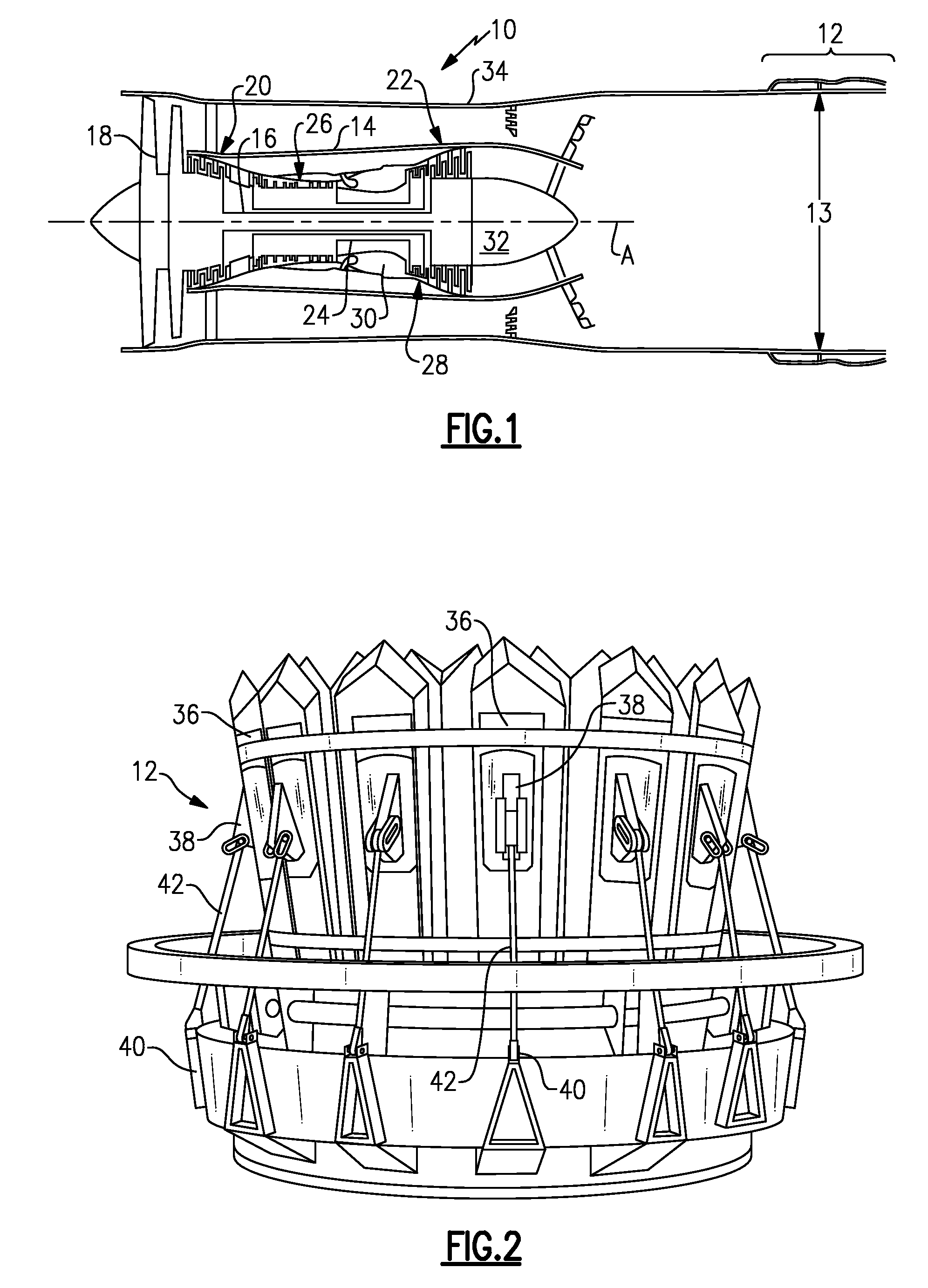
[0014]A turbofan engine 10 is shown schematically in FIG. 1. As known, a fan section moves air and rotates about an axis A. A compressor section, a combustion section, and a turbine section are also centered on the axis A. FIG. 1 is a highly schematic view, however, it does show the main components of the gas turbine engine. Further, while a particular type of gas turbine engine is illustrated in this figure, it should be understood that the claim scope extends to other types of gas turbine engines.

[0015]The engine 10 includes an exhaust nozzle 12 for varying the nozzle exit area 13 to achieve a desired thrust. The engine 10 includes a core 14 housing a low spool 16. A fan 18, low pressure compressor 20 and low pressure turbine 22 are mounted on the low spool 16. A high spool 24 is arranged coaxially relative to the low spool 16. A high pressure compressor 26 and high pressure turbine 28 are mounted on the high spool 24. A combustor 30 is arranged between the high pressure compressor 2


PUM


Abstract

In one example, a gas turbine engine includes an exhaust nozzle. The exhaust nozzle includes a flap supported relative to a static structure by a strut. The flap includes a backbone providing a slot. A slider interconnects a strut end to the backbone. In one example, the slider includes a body that is slidingly received within the slot. A boss extends from the body and provides a first feature. The strut end includes a second feature that cooperates with the first feature to prevent relative rotation between the slider and a portion of the strut end.

Description


Claims


Application Information

Patent Timeline
Owner RAYTHEON TECH CORP
Why Eureka
Try Eureka