Method and Device For Checking the Function For Inverting the Polarity on a Subscriber Line Comprising a Plurality of Wires

a subscriber line and function technology, applied in the direction of substation equipment, electrical apparatus, supervision/monitoring/testing arrangements, etc., can solve the problems of needing to operate appropriately by additional personnel and external measuring equipment described above, so as to avoid additional personnel and financial involvement.

Active Publication Date: 2008-10-16
RPX CORP
View PDF8 Cites 0 Cited by
  • Summary
  • Abstract
  • Description
  • Claims
  • Application Information

AI Technical Summary

Benefits of technology

The present invention provides an improved method for testing the functionality of a communication system's network interface (NIC). By avoiding the use of extra hardware or human resources, it becomes easier to test the NIC's functions properly. This helps reduce costs and improve efficiency.

Problems solved by technology

The technical problem addressed in this patent text is how to verify if a subscriber line module allows for multiple different types of reverse polarization on its wires without requiring extra equipment like an external measuring device.

Method used


Image

  • Method and Device For Checking the Function For Inverting the Polarity on a Subscriber Line Comprising a Plurality of Wires
  • Method and Device For Checking the Function For Inverting the Polarity on a Subscriber Line Comprising a Plurality of Wires
  • Method and Device For Checking the Function For Inverting the Polarity on a Subscriber Line Comprising a Plurality of Wires

Examples


Embodiment Construction

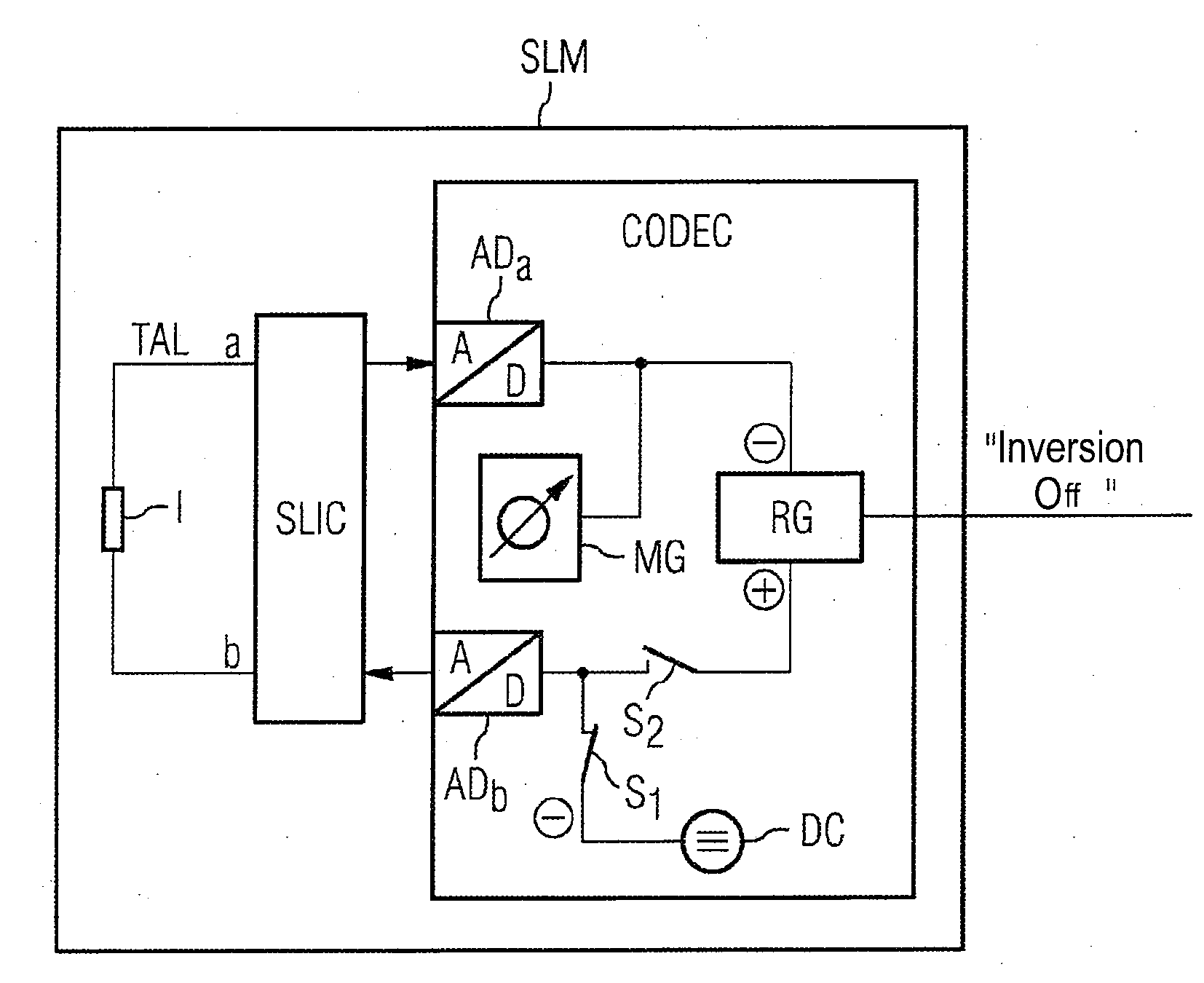
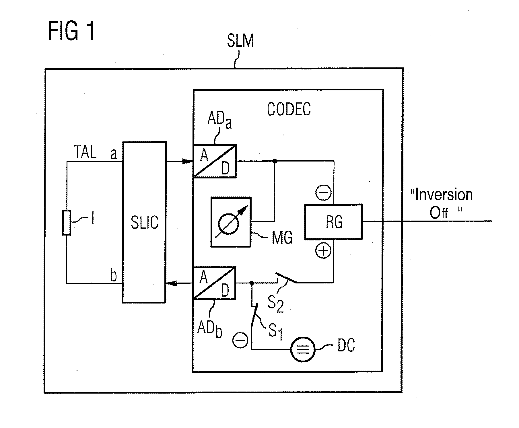
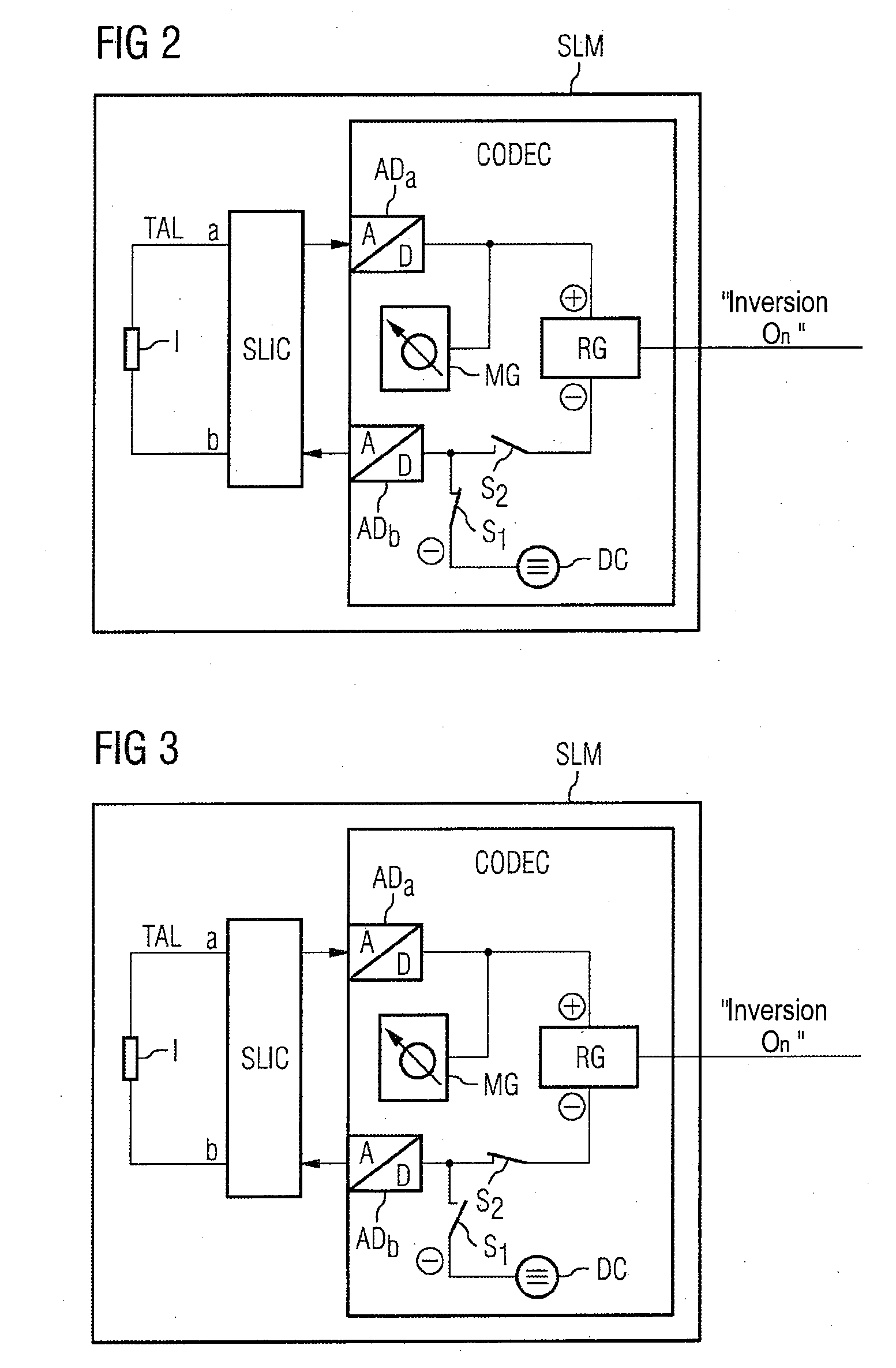
[0021]The text below describes the schematic design of a subscriber line module in a conventional communication network for performing the invention with reference to FIGS. 1, 2 and 3.

[0022]In this example, a test impedance I has been connected between two wires a and b of a subscriber line TAL at the exchange end (not shown). When this test impedance I is switched in, the subscriber is simultaneously isolated from the exchange, which prevents any disruption to the subscriber during the check.

[0023]The subscriber line TAL is connected to a subscriber line interface circuit SLIC, which in turn represents the interface to an encoder / decoder CODEC at the exchange (not shown).

[0024]The CODEC comprises a respective analog / digital converter ADa, ADb for each of the wires a, b of the subscriber line TAL and an inversion device (“reversal generator”—RG), a direct current source (“DC generator”—DC) and a measuring instrument MG.

[0025]The inversion device RG can be switched to a plurality of


PUM


Abstract

The invention relates to a method and to a device for testing the function for inverting the polarity on a subscriber connection line (TAL) comprising several wires (a, b), in order to connect at least one subscriber to a subscriber connection line (SLM), which comprises at least one inverting device (RG) and a current measuring device (MG) which is associated with the inverting device (RG). In a first step, the subscriber connection component (SLM) is separated from the inverting device (RG) and forces physical inversion on the wires (a, b) of the subscriber connection line (TAL). In a second step, the inverting function of the inverting device (RG) is activated. In a subsequent third step, the subscriber connection component (SLM) is separated from the device (DC) which forces the physical inversion and is connected to the inverting device (RG). The correct function of inversion is tested during all three steps by measuring the direction of the current flow.

Description


Claims


Application Information

Patent Timeline
Owner RPX CORP
Why Eureka
Try Eureka