Polarized light emitting diode

a light-emitting diode and polarized technology, applied in the direction of lasers, optical resonator shape and construction, semiconductor lasers, etc., can solve the problems that the technology described above has not been presented, and achieve the effect of reducing the total number of parts and reducing the manufacturing cost of lcds

Active Publication Date: 2008-11-27
KOREA UNIV IND & ACADEMIC CALLABORATION FOUND
View PDF3 Cites 13 Cited by
  • Summary
  • Abstract
  • Description
  • Claims
  • Application Information

AI Technical Summary

Benefits of technology

The technical effect of this patented technology is that it allows for more efficient use of LED's while maintaining their quality level or performance levels at competitive prices compared with traditional methods like adding extra layers on top of existing components.

Problems solved by technology

This patented technical problem addressed in this patents relates to reducing power consumption during operation of electronic equipment due to its own unique design features. Specifically, current methods involve adding extra components on top of existing ones, making them difficult to control their properties accurately over large areas. Therefore, new ways to achieve desired performance levels while minimizing energy usage would provide significant benefits.

Method used


Image

  • Polarized light emitting diode
  • Polarized light emitting diode
  • Polarized light emitting diode

Examples


Embodiment Construction

[0022]Hereinafter, a preferred embodiment of the present invention will be explained in detail with reference to the accompanying drawings.

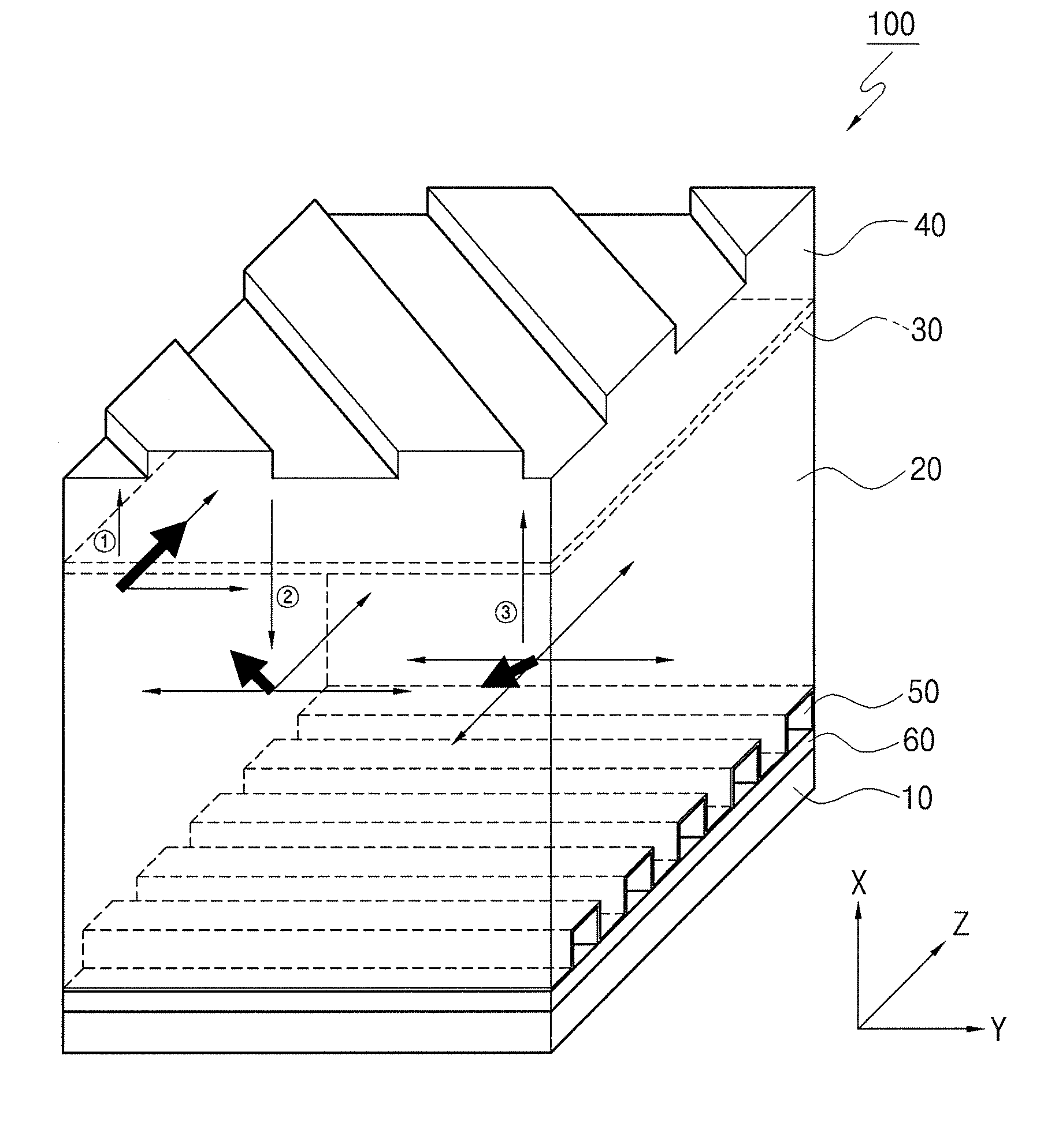
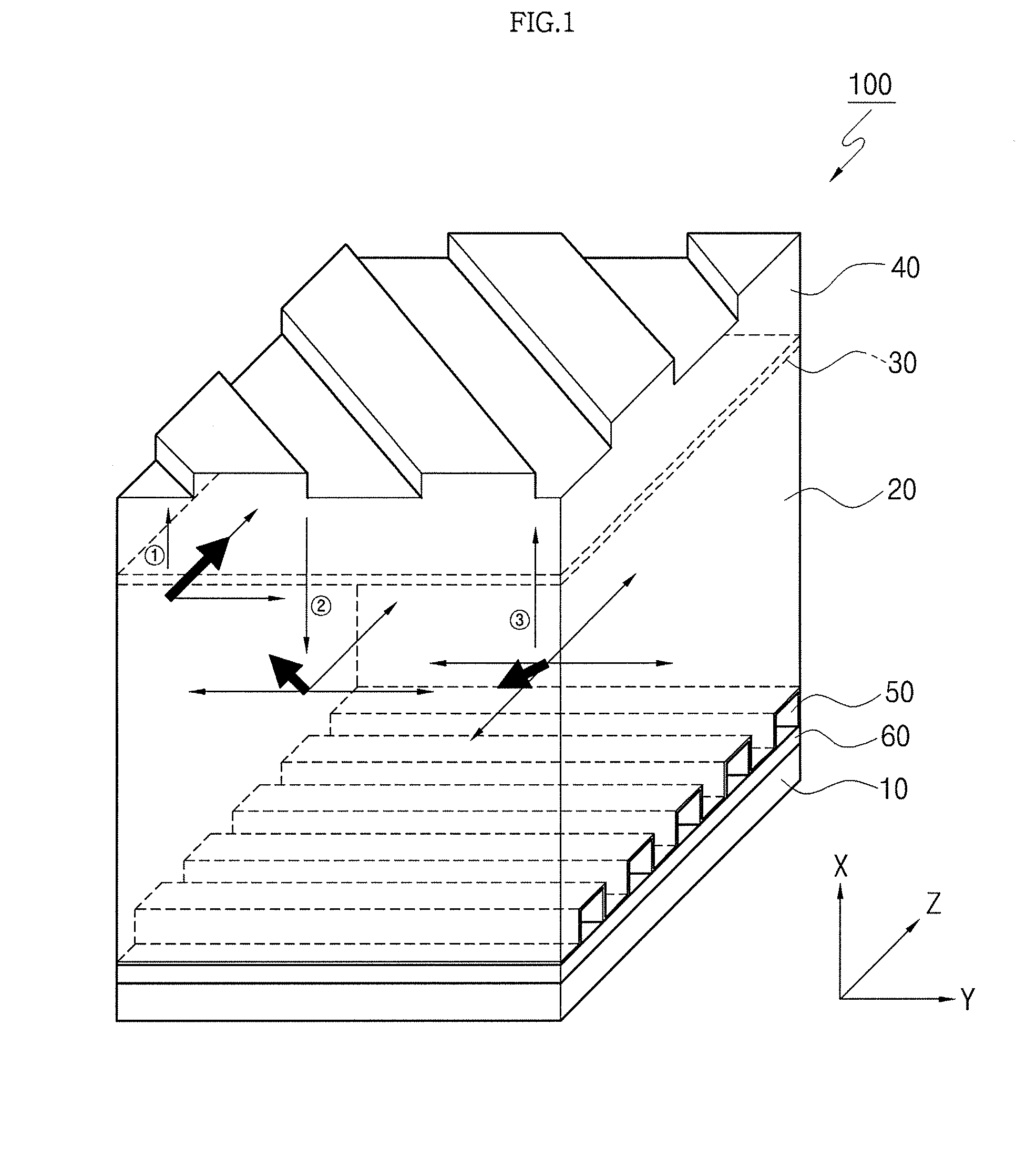
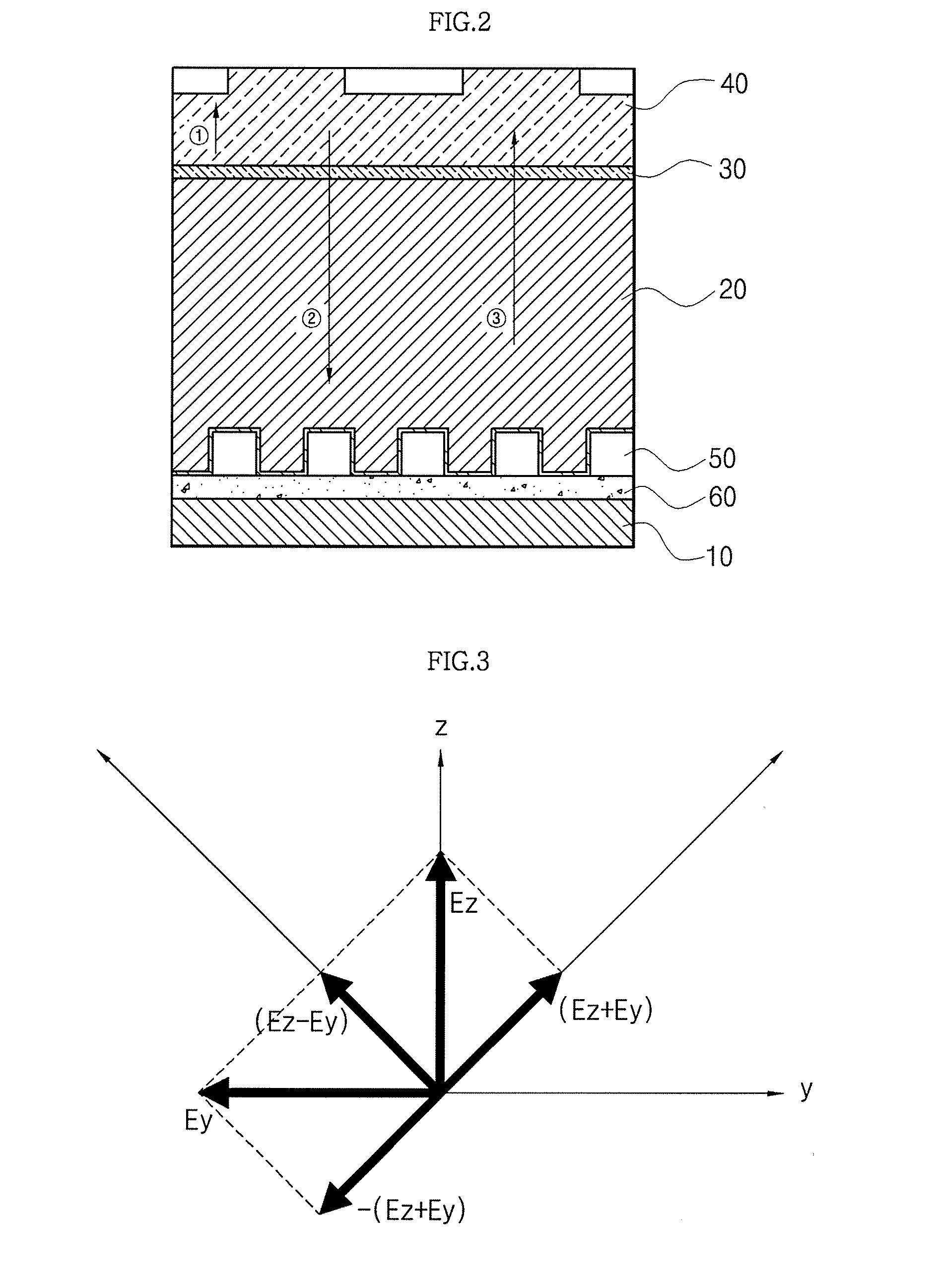
[0023]FIG. 1 is a perspective view of a polarized LED according to the present invention and FIG. 2 is a sectional view of the polarized LED according to the present invention.

[0024]As shown in FIGS. 1 and 2, the polarized LED 100 according to the present invention comprises a nitride thin film 20 formed on a substrate 10, and a quantum well layer 30 formed on the nitride thin film 20. Preferably, the nitride thin film 20 includes at least one of GaN, InN and AlN and the substrate 10 includes a sapphire substrate.

[0025]According to the present invention, the structure of the LED 100 comprising the elements as described above is modified and improved. In detail the LED 100 has a structure for emitting most light, which is generated from the quantum well layer 30, in the front direction thereof.

[0026]As described above, in order to emit most of the li


PUM


Abstract

Disclosed is a polarized light emitting diode (LED) capable of emitting polarized light in the front direction thereof by forming a first grating layer on a quantum well layer and forming a second grating layer on a substrate. The polarized LED includes a nitride thin film formed on a substrate, a quantum well layer formed on the nitride thin film, a first grating layer formed on the quantum well layer to allow a part of light generated from the quantum well layer to pass through the first grating layer and to reflect remaining light, and a second grating layer formed on the substrate to rotate the light reflected from the first grating layer such that the reflected light passes through the first grating layer.

Description


Claims


Application Information

Patent Timeline
Owner KOREA UNIV IND & ACADEMIC CALLABORATION FOUND
Why Eureka
Try Eureka