Compact radar test range

Inactive Publication Date: 2009-02-19
GENERAL ATOMICS
View PDF16 Cites 11 Cited by
  • Summary
  • Abstract
  • Description
  • Claims
  • Application Information

AI Technical Summary

Problems solved by technology

Because of limited access to airplanes and the high cost of testing radars on aircraft, however, there is a need to find a substitute for some aspects of the flight test and burn-in when a radar system needs to be tested.
The problem with the ISAR scheme is that the minimum range at which the radar can work is often very large.
Additionally, there may be other difficulties with such a rapid switching in other parts of the radar circuitry, notably in the digital waveform synthesizer.
Moreover, working at such minimum ranges is very different from the normal operation of the radar, where ranges of the order

Method used


Image

  • Compact radar test range
  • Compact radar test range
  • Compact radar test range

Examples


Embodiment Construction

[0032]The following description is not to be taken in a limiting sense, but is made merely for the purpose of describing the general principles of the invention. The scope of the invention should be determined with reference to the claims. The present embodiments address the problems described in the background while also addressing other additional problems as will be seen from the following detailed description.

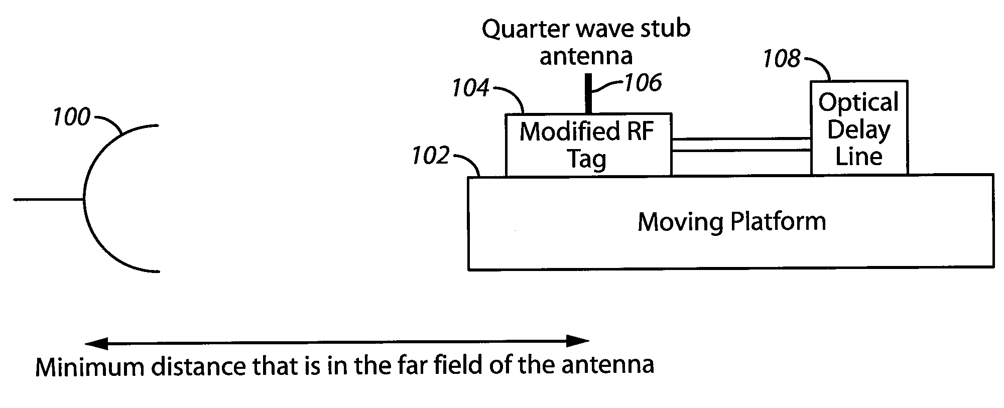
[0033]Referring to FIG. 1, a diagram is shown illustrating a compact radar test range. Shown is a radar 100, a moving platform 102, a tag 104, an antenna 106, and a delay 108.

[0034]In some embodiments, the radar 100 is placed at least a minimum distance that is in the far field of an antenna of the radar. In some embodiments, the compact radar test range requires distances of 25 meters or less from the radar 100 to the antenna 106. Additionally, the compact radar test range is preferably situated indoors. The tag 104 is coupled to the antenna 106 and the delay 108 and is mount


PUM


Abstract

A system for testing radar in accordance with one embodiment comprising a target motion platform; a target motion platform controller for controlling motion of the platform; a radar responsive tag and a delay line located on the target motion platform; the radar which is being tested; and a motion measurement simulator for inputting data to the radar electronics assembly to simulate movement of the radar. In some embodiments the system further comprises a radar motion platform, wherein the radar electronics assembly is positioned on the radar motion platform; a radar motion platform controller for controlling the movement of the radar motion platform; and a master controller coupled to the radar motion platform controller and the target motion platform controller.

Description


Claims


Application Information

Patent Timeline
Owner GENERAL ATOMICS
Why Eureka
Try Eureka