X-Ray CT Apparatus

a technology of ct apparatus and x-ray, which is applied in the direction of material analysis, tomography, instruments, etc., can solve the problem of a smaller number of development proposals of industrial x-ray ct apparatus, and achieve the effect of easy change of resolution (that is, the imaging area)

Inactive Publication Date: 2009-02-19
RIGAKU CORP
View PDF5 Cites 8 Cited by
  • Summary
  • Abstract
  • Description
  • Claims
  • Application Information

AI Technical Summary

Benefits of technology

The present invention provides an x-ray computed tomography machine with a rotating support member that allows for easy rotation of the sample while scanning it. This design makes it possible to scan samples without rotating them, allowing for better quality images of fluids and smaller objects. Additionally, the machine has two parts - one part holds the X-ray source and another part moves towards and away from the sample holder. By moving these components together, the machine's ability to achieve high image quality results.

Problems solved by technology

This patent describes an X-ray computed tomography machine that can accurately determine the density distribution of different types of radiation transmitting objects. It achieves this by measuring the intensity of X rays passing through them while they hit a special type of sensor called an x-ray detector. By analyzing these measurements, the machine can create detailed 3D image data about the objects being scanned. Additionally, the machine allows for easy adjustment of its imaging range and resolution based on the desired results.

Method used


Image

  • X-Ray CT Apparatus
  • X-Ray CT Apparatus
  • X-Ray CT Apparatus

Examples


Embodiment Construction

[0043]An embodiment of the present invention will be described hereunder in detail with reference to the drawings.

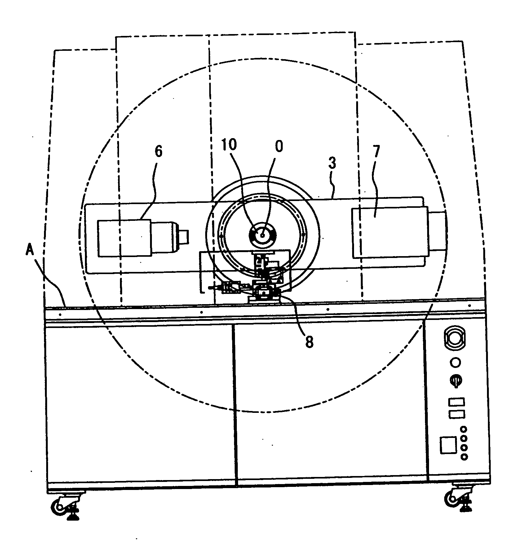
[0044]FIG. 3 is a front view showing an X-ray CT apparatus according to an embodiment of the present invention, and FIG. 4 is a side perspective view showing the X-ray CT apparatus. First, the overall construction of the X-ray CT apparatus according to the embodiment will be described with reference to these drawings.

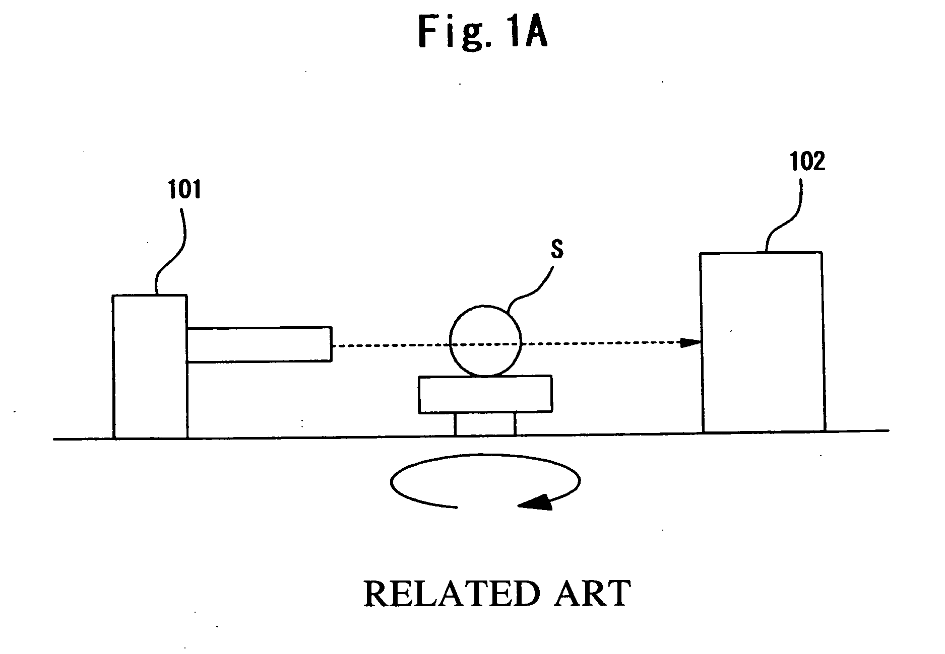
[0045]As shown in FIG. 4, a bearing stand 1 is mounted at a position near to the rear portion of the top surface of a table A of the main body of the X-ray CT apparatus. The bearing stand 1 is provided with a cylindrical bearing 2, and the center portion of a guide arm 3 (rotational support member) is freely rotatably mounted to the bearing 2. Here, the center axis of the bearing 2 corresponds to a rotational axis O of the guide arm 3, and the rotational axis O extends in the horizontal direction. A sample S is disposed on the rotational axis O (horizontal axis


PUM


Abstract

In an X-ray CT apparatus, an X-ray source and an X-ray detector mounted in a guide arm are freely movable in such a direction as to approach to and separate from a sample. With respect to this movement, the center of gravity of the whole containing respective constituent elements mounted in the guide arm is kept on the rotational axis by a weight balance adjusting mechanism. The weight balance adjusting mechanism contains a movable weight which is freely movable to the guide arm. The movement of the movable weight is controlled so that a difference between the rotational moment around the rotational axis is offset and substantially equal to zero. The moving passage of the movable weight is set on a straight line which is parallel to the moving direction of the X-ray source and the X-ray detector and does not pass through the rotational axis.

Description


Claims


Application Information

Patent Timeline
Owner RIGAKU CORP
Why Eureka
Try Eureka