Lock body

a technology of lock body and lock body, which is applied in the field of lock body, can solve the problems of false alarm and user's accidental use of the knob

Inactive Publication Date: 2009-07-16
ABLOY OY
View PDF23 Cites 28 Cited by
  • Summary
  • Abstract
  • Description
  • Claims
  • Application Information

AI Technical Summary

Benefits of technology

This invention relates to an electronic device called a lock mechanism used for controlling access to certain areas or objects. It includes a lock body with two surfaces - one on top of another and a force transmitting/controlling system. One surface can be fixed to the lock body while the other surface has a matching surface that matches with the force transmitting surface. When the lock body rotates, its mated surface touches the force transmitting surface, allowing the electric motor to move the follower backward. Another surface acts like a linkage between them, allowing the electric motor to rotate the follower forward when needed.

Problems solved by technology

This patent describes how an electrical motor can be used to switch between locked states and unlocked states. However, it does have technical drawbacks such as being able to easily break down the dome on the knob without triggering any alarms, exposure of the dome from damage caused by accidental use, and potential security concerns due to the possibility of unauthorized access.

Method used


Image

  • Lock body
  • Lock body
  • Lock body

Examples


Embodiment Construction

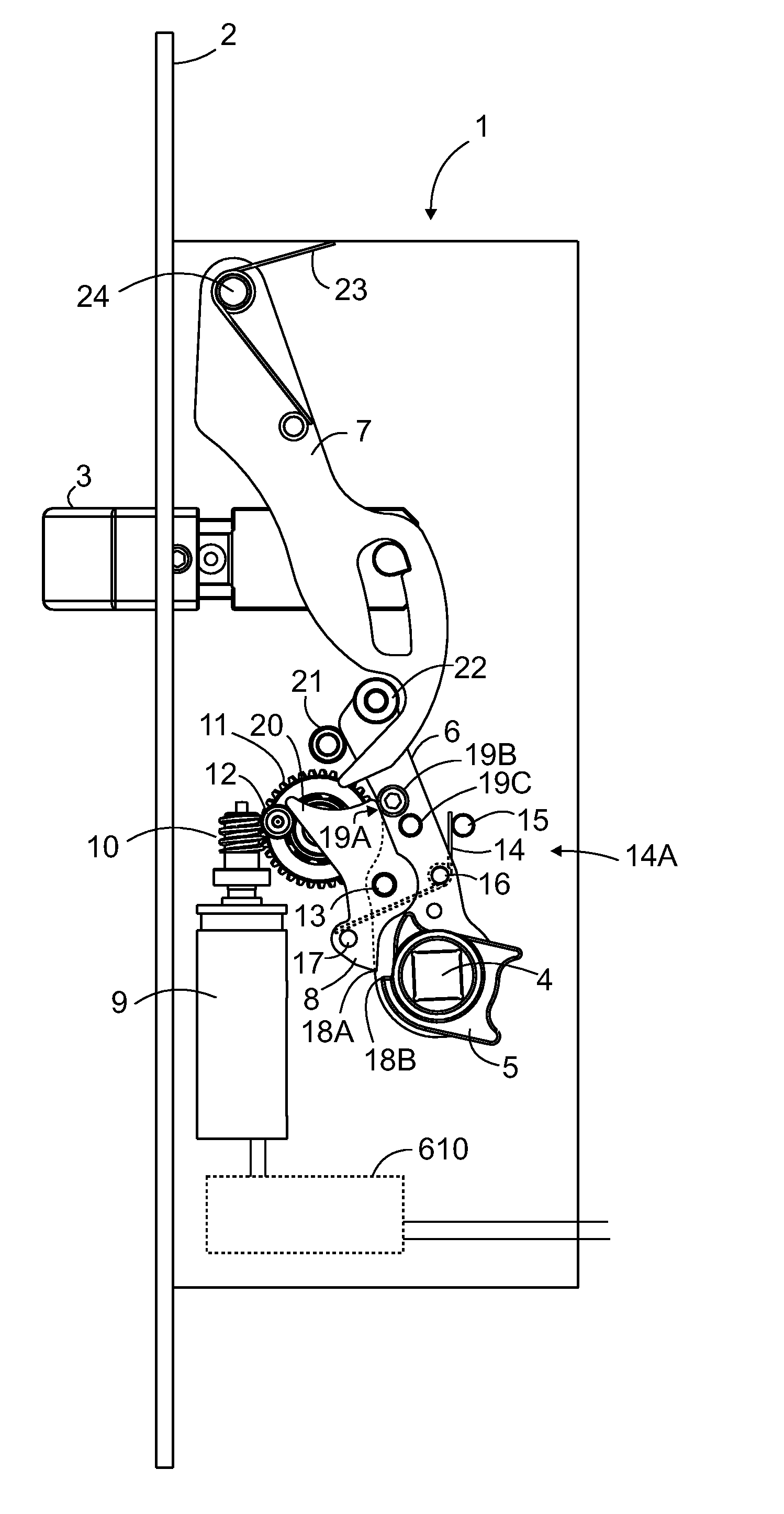
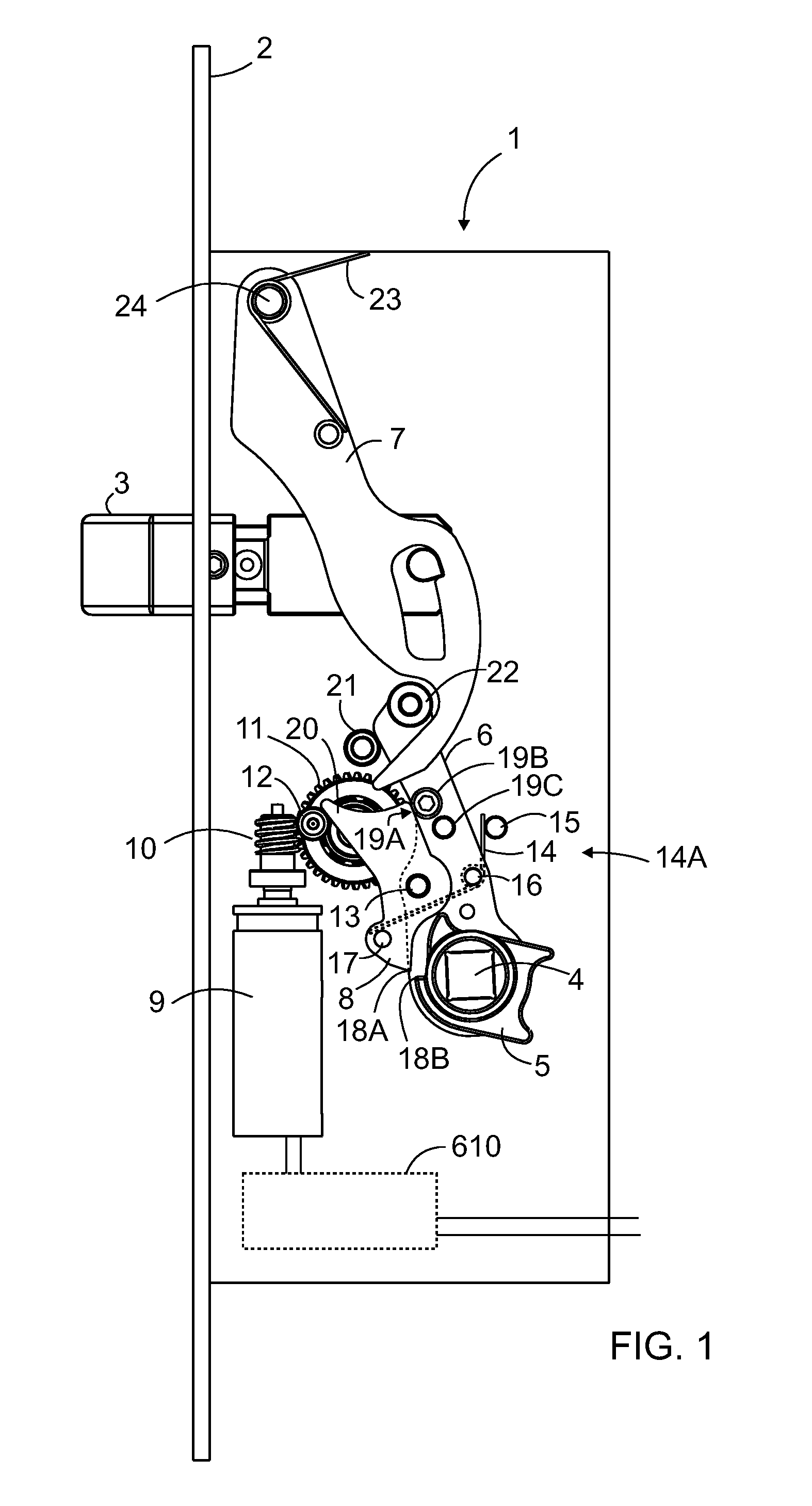
[0017]FIG. 1 illustrates an example of a lock body 1 according to the invention. The bolt 3 is out—that is, the end of the bolt forms a barring projection in relation to the front plate 2 of the lock body.

[0018]The extrusion length of the bolt in relation to the front plate can be 14 or 20 mm, for example. The follower 6 is under motor control in the state illustrated in FIG. 1.

[0019]In addition to the bolt, the lock body 1 comprises a follower 6 that is functionally connectable with the bolt 3 to control the position of the bolt, and a driver 5. The driver is connectable with the follower to convey force turning the driver to the follower. It is also possible that there are separate drivers on both sides of the follower, one of which has a solid transmission link to the follower while the other has a connectable force transmission link to the follower. In this case, a divided spindle is used in place of a uniform spindle.

[0020]In a normal installation configuration, the driver is conn


PUM


Abstract

A lock body includes a bolt and a follower that is functionally connectable with the bolt to control the position of the bolt, and a driver. The driver is connectable with the follower to convey force turning the driver to the follower. Furthermore, the lock body includes an electric motor to operate as a power source for changing the locking state of the lock body.

Description


Claims


Application Information

Patent Timeline
Owner ABLOY OY
Why Eureka
Try Eureka