Backlight
a backlight and light technology, applied in the field of backlights, can solve the problems of low light efficiency, low light efficiency, and low light efficiency, and achieve the effects of improving light efficiency and display uniformity, reducing cost, and improving display quality
- Summary
- Abstract
- Description
- Claims
- Application Information
AI Technical Summary
Benefits of technology
Problems solved by technology
Method used
Image

Examples
first embodiment
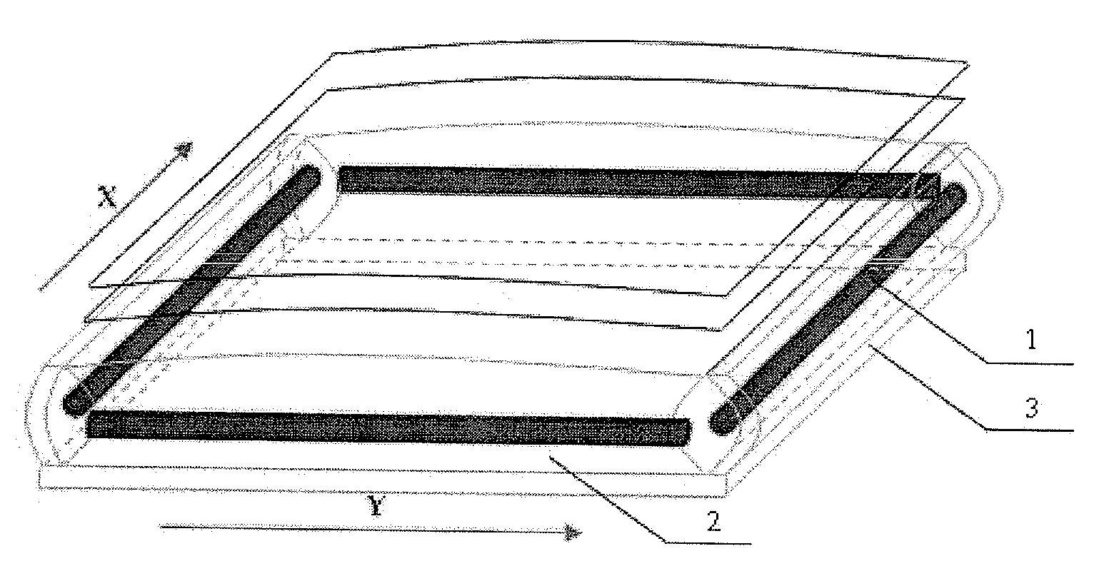
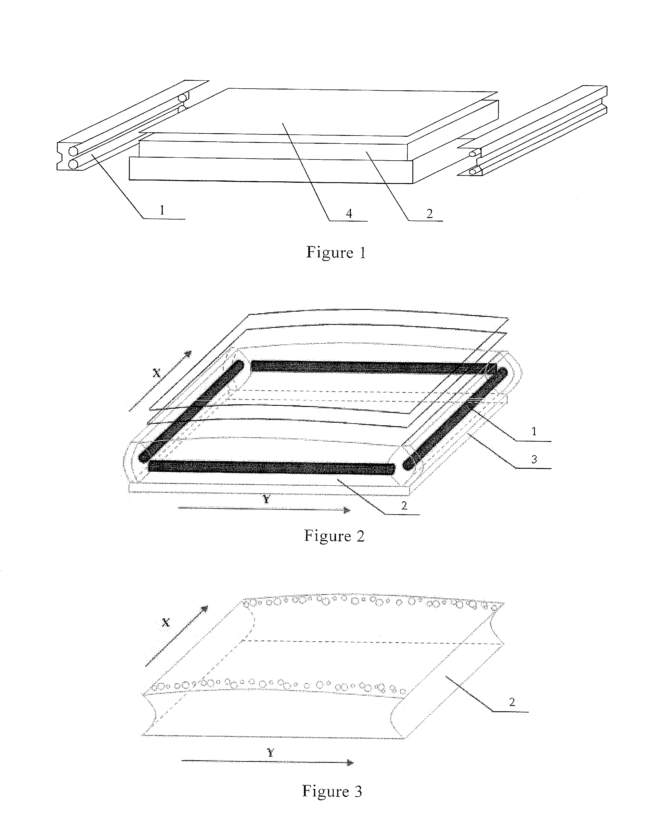
[0020]FIG. 2 is a schematic view of a backlight according to the first embodiment of the present invention. As shown in FIG. 2, the backlight comprises a back cover 3 with a bottom plate and side covers, a light guide plate 2 disposed on the bottom plate of the back cover 3, and two cold cathode fluorescence lamps (CCFLs) 1 located on the sides of the light guide plate 2. The CCFLs 1 are lamps in “L” shape. Each CCFL is disposed on two adjacent sides of the light guide plate 2 in such a manner that the high voltage ends of the two CCFLs are disposed diagonally opposing to each other. For example, the two CCFLs in L shape can be disposed as following. The high voltage end of the first CCFL in L shape is disposed at upper left corner while the high voltage end of the second CCFL in L shape is disposed at lower right corner. Alternatively, the high voltage end of the first CFFL in L shape is disposed at lower left corner while the high voltage end of the second CCFL in L shape is disposed
second embodiment
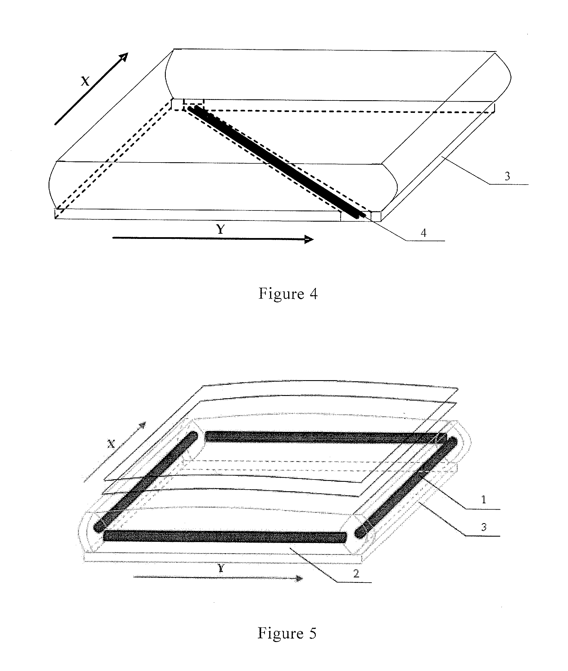
[0028]FIG. 5 is a schematic view of a backlight according to the second embodiment of the present invention. As shown in FIG. 5, the backlight comprises a back cover 3 with a bottom plate and side covers, a light guide plate 2 disposed on the bottom plate of the back cover 3, and cold cathode fluorescence lamps (CCFLs) 1 located on the sides of the light guide plate 2. The CCFLs 1 comprise four lamps in a straight line shape. Each CCFL is disposed on one side of the light guide plate 2 in such a manner that the high voltage end of one CCFL is disposed adjacent to the low voltage end of another CCFL.
[0029]Since the CCFL emits light with the mercury ions inside the high voltage ionization tube, more mercury ions are activated near the high voltage end compared with the low voltage end of the CCFL, and in turn the high voltage end of the CCFL is brighter than the low voltage end of the CCFL. According to the backlight of the present embodiment, the brighter high voltage end of one CCFL is
PUM
 Abstract
Description
Claims
Application Information
 - R&D Engineer
- R&D Manager
- IP Professional
- Industry Leading Data Capabilities
- Powerful AI technology
- Patent DNA Extraction
Browse by: Latest US Patents, China's latest patents, Technical Efficacy Thesaurus, Application Domain, Technology Topic.
© 2024 PatSnap. All rights reserved.Legal|Privacy policy|Modern Slavery Act Transparency Statement|Sitemap