Structure For A Suction Device

a suction device and structure technology, applied in the field of suction devices, can solve the problems of restricted placement, unglued, unmovable, etc., and achieve the effect of enhancing the suction durability

Active Publication Date: 2010-05-13
FAN EAGLE
View PDF10 Cites 12 Cited by
  • Summary
  • Abstract
  • Description
  • Claims
  • Application Information

AI Technical Summary

Benefits of technology

The technical effect of this patented design is that it improves how well an aspirator works when used with different materials or surfaces without losing its ability to work properly over time due to wear out issues such as abrasions caused by contact between parts during use.

Problems solved by technology

This patented technical problem addressed by this patents relates to improving the performance of an existing sucking device used during medical procedures such as surgeries or dentistry operations where it becomes necessary to hang objects onto surfaces without causing damage.

Method used


Image

  • Structure For A Suction Device
  • Structure For A Suction Device
  • Structure For A Suction Device

Examples


Embodiment Construction

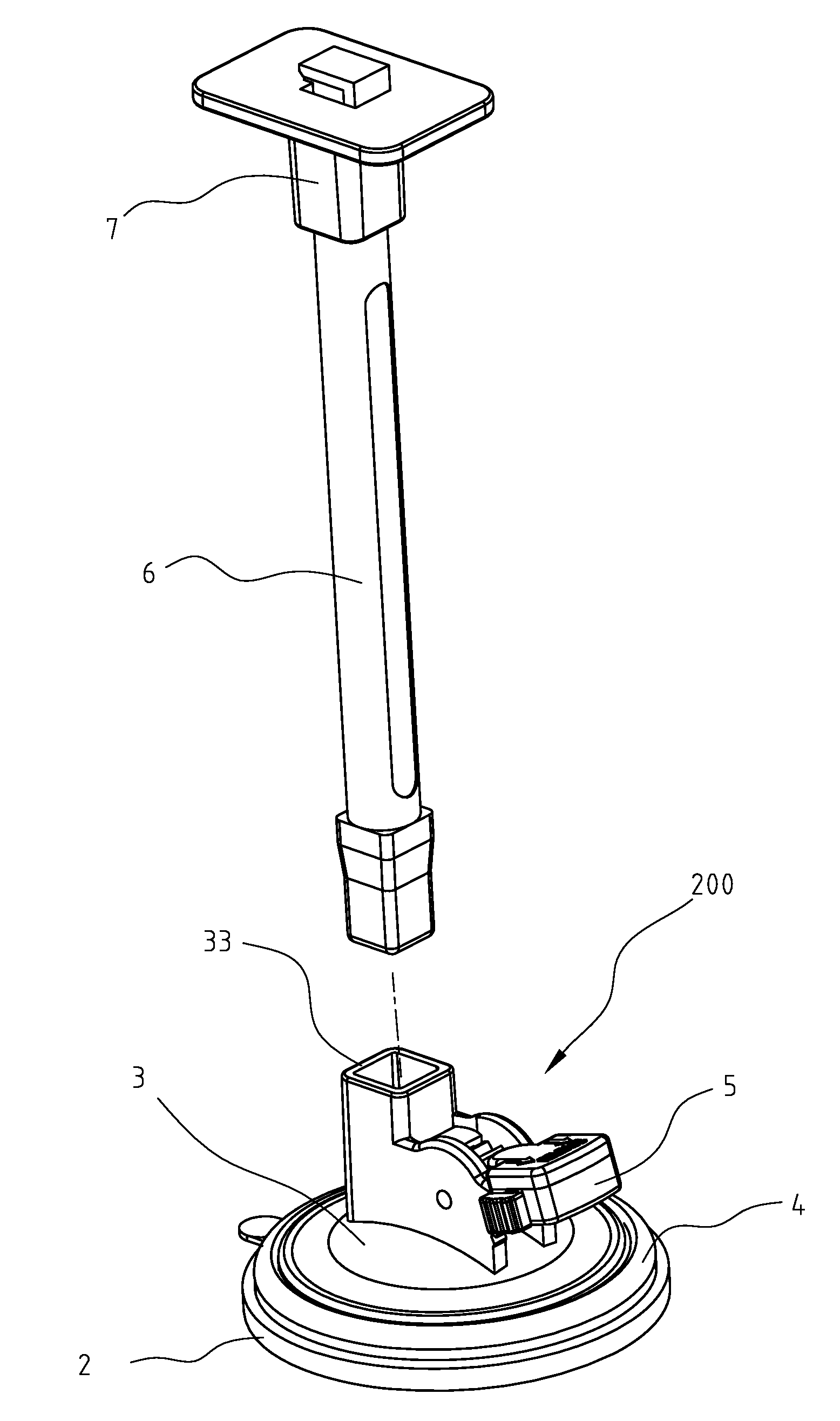
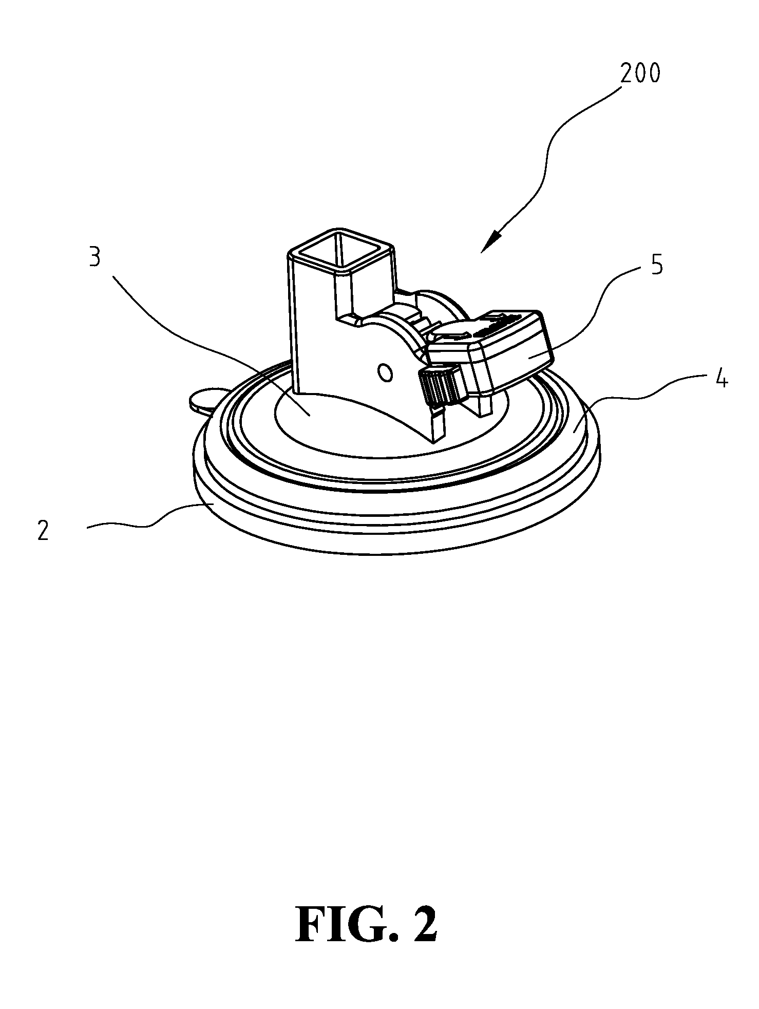
[0017]FIGS. 2 & 3 show a three-dimensional view and a dissected view of the present invention. Suction device 200 of the present invention includes a suction unit 2, a fixing unit 3, a press unit 4 and a linkage positioning 5. Suction unit 2 includes a suction disc 21 and a pulling element 22. The bottom of suction disc 21 is made of a soft material and has a shape of flat surface. Pulling element 22 is pillar-shaped, with the bottom engaged to the central area of the top of suction disc 21. Fixing unit 3 is a shell convex at the central area, located on top of suction disc 21 of suction unit 2. The central area of fixing unit 3 further includes a channel hole 31. Pulling element 22 of suction unit 2 extends through channel hole 31 to above fixing unit 3. Press unit 4 is of a ring shape made of rigid, non-deformable material. Press unit 4 is restricted between the area close to circumference of the bottom of fixing unit 3 and the top surface of suction disc 21 of suction unit 2. Linkag


PUM


Abstract

A suction device is provided, including a suction unit, a fixing unit, a press unit and a linkage positioning unit. The fixing unit is located on top of the suction unit. The press unit is restricted between the area close to circumference of the fixing unit and the top surface of the suction unit. The linkage positioning unit is fixed to above the fixing unit and performs linked movement with the pulling element of the suction unit. When the fixing unit tilts partially by the exerted force of a hanging object, the press unit can still press tightly against the area close to the circumference of the suction unit to maintain a strong suction hold and improve the suction durability.

Description


Claims


Application Information

Patent Timeline
Owner FAN EAGLE
Why Eureka
Try Eureka