Vibration damping control device of a diesel engine vehicle

Inactive Publication Date: 2010-09-09
TOYOTA JIDOSHA KK
View PDF10 Cites 18 Cited by
  • Summary
  • Abstract
  • Description
  • Claims
  • Application Information

AI Technical Summary

Benefits of technology

[0016]According to the control gain determining portion as described above, a control gain is decreased when a compensation component value by the vibration damping control deviates from a restriction range for variation of a fuel injection quantity, and the control gain is increased when the compensation component value does not deviate from the restriction range. That is, in this case, the control gain is set so as to increase or to decrease depending upon the relation between a restriction range for variation of a fuel injection quantity and the variation of the fuel injection quantity corresponding to the compensation component. With this manner, strictly speaking, just before the decreasing of a control gain, a compensation component value deviates from a restriction range for variation of a fuel injection quantity; however, after this, the compensation component is decreased so as not to suffer the restriction for the variation of the fuel injection quantity, so that, substantially, the wave forms of varying components corresponding to the compensation component of the vibration damping control can be reflected, with almost no deformation of the wave form (with almost no changing of the frequency characteristic and phase characteristic) and also without unnecessary decrease of the oscillational amplitude, in the requested value or execution amount of a fuel injection quantity, as a control command, given to the engine.
[0017]In this regard, as described above, preferably, the changing of a control gain is performed at a time point when the sign of a compensation component value is reversed. At the time point of the reversion of the sign of a compensation component value, the compensation component value becomes 0, and thus, advantageously, the compensation component can be smoothly varied around before and after the change of the control gain, and also the avoiding of a sudden change of a driving torque or a wheel torque corresponding to the compensation component will become easy. Accordingly, as understood from the above-mentioned structure, in the first aspect of the present invention, if a compensation component value deviates from a restriction range for variation of a fuel injection quantity, the decreasing of a control gain will be executed at the first time point of the reversion of the sign of the compensation component value after the occurrence of the deviation. And, at a time point of the reversion of the sign of a compensation component value, if the compensation component value has not deviated from a restriction range for variation of a fuel injection quantity between the present time point and the time point of the preceding reversion of the sign of the compensation component value, the increase of a control gain is executed.
[0018]Furthermore, regarding the change of a control gain in the first aspect of the present invention, while the decrease of a control gain should be quickly executed, the increase of the control gain is not needed to execute immediately after a compensation component value does not deviate from a restriction range for variation of a fuel injection quantity. Rather, if a once decreased control gain is increased immediately, a compensation component value would deviate again f

Problems solved by technology

In this regard, in fuel injection quantity controls for diesel engines, there is a case in which it is required to set out a restriction for the variation width of a fuel injection quantity, and, in this case, it has been found that a variation of a fuel injection quantity (variation of a wheel torque) requested by a vibration damping control cannot be achieved, so that a vehicle body vibration cannot be well suppressed and, in some occasions, a request of a driving torque from a vibration damping control may induce an effect of amplification of a vehicle body vibration, such as

Method used


Image

  • Vibration damping control device of a diesel engine vehicle
  • Vibration damping control device of a diesel engine vehicle
  • Vibration damping control device of a diesel engine vehicle

Examples


Embodiment Construction

[0033]The present invention is explained in detail with respect several preferable embodiments, referring to the drawings accompanying in the following. In the drawings, the same reference numeral indicates the same portion.

[0034]Structures of the Device

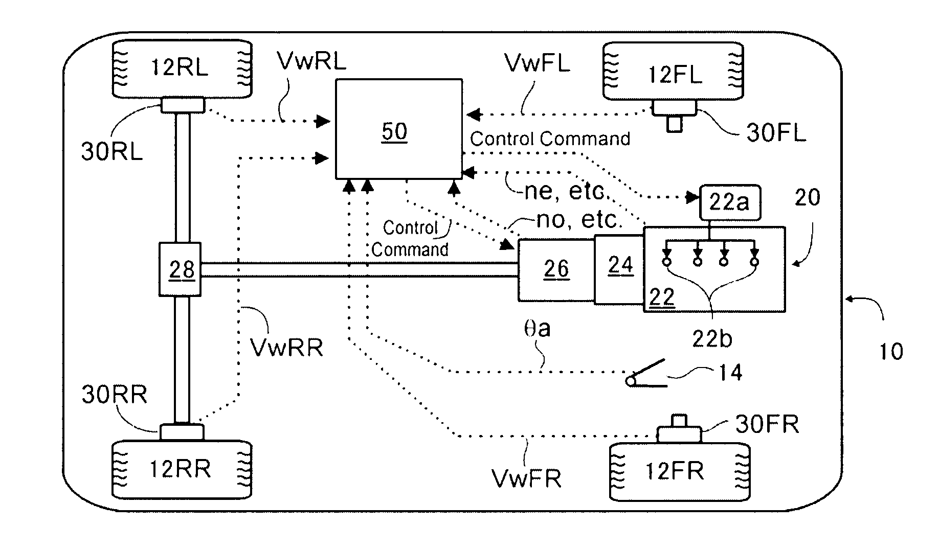
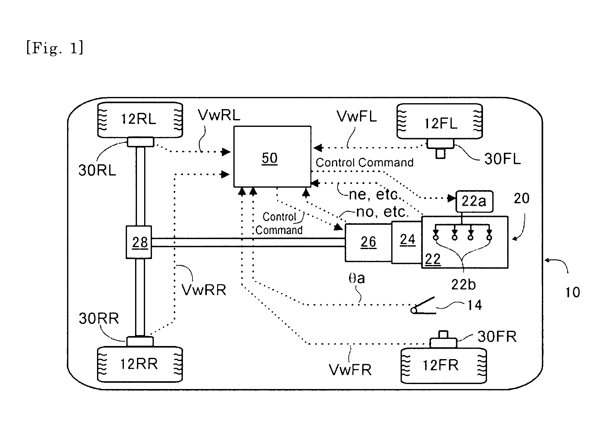
[0035]FIG. 1 schematically shows a vehicle, such as an automobile, in which a preferable embodiment of the inventive vibration damping control device is installed. In this drawing, in the vehicle 10 having left and right front wheels 12FL and 12FR and left and right rear wheels 12RL and 12RR, there is installed a driving device 20 which generates a driving force or a driving torque in the rear wheels according to the depression of an accelerator pedal 14 by a driver in a usual manner. In the shown example, the driving device 20 is constructed such that a driving torque or a rotational driving force is transmitted from an engine 22 through a torque converter 24, an automatic transmission 26, a differential gear 28, etc., to the rear whee


PUM


Abstract

The vibration damping control device which performs damping of vibration of a vehicle body through a driving output control of a diesel vehicle in accordance with the present invention comprises a compensation component computing portion which computes a compensation component which compensates a wheel torque to suppress an amplitude of vehicle body vibration; and a control gain determining portion which determines a control gain for the compensation component, wherein, at a time point of reversion of the sign of the value of the compensation component, the control gain determining portion decreases the control gain when, before that time point, the value of the compensation component has deviated from a restriction range for variation of a fuel injection quantity determined based on engine operational condition, and increases the control gain when the value of the compensation component has not deviated from a restriction range for variation of a fuel injection quantity. Thereby, in the execution of the restriction of the fuel injection quantity variation, the wave form of the compensation component of the vibration damping control is maintained, and also, the effect of the vibration damping control becomes as large as possible.

Description


Claims


Application Information

Patent Timeline
Owner TOYOTA JIDOSHA KK
Why Eureka
Try Eureka