Orthotic lift apparatus

a technology of orthopaedic lifts and lifting components, applied in the field of orthopaedic lifts, can solve the problems of affecting the use of the foot lift, and immobilizing the working muscles to a degree, and achieves the effects of convenient use, reliable and long-use foot lift components, and convenient attachmen

Active Publication Date: 2010-12-23
KILLIAN JAMES DR
View PDF27 Cites 7 Cited by
  • Summary
  • Abstract
  • Description
  • Claims
  • Application Information

AI Technical Summary

Benefits of technology

This patent describes a foot-drop exercise machine that has several technical features: it allows patients to have independent control over their legs and feet, making them easier to work with and less dependent upon others who cannot physically support themselves. Additionally, this machine helps people with nearsightedness experience pain when trying to walk again after being temporarily lifted up. Overall, these machines improve physical therapy and reduce dependency on care providers.

Problems solved by technology

This patent describes various technical features related to improving foot drop training and preventing foot drop injuries during physical therapy sessions. These improvements include using elastic materials to support the weight of the legs, providing stability through movement, and attaching the feet to crutches or other tools to improve mobility. Additionally, there may be some devices that act directly on the foot to enhance its activity. Overall, these technical features aim to reduce pain and promote better overall performance of the treatment session.

Method used


Image

  • Orthotic lift apparatus
  • Orthotic lift apparatus
  • Orthotic lift apparatus

Examples


Embodiment Construction

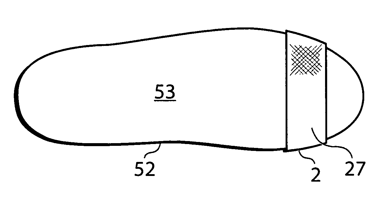
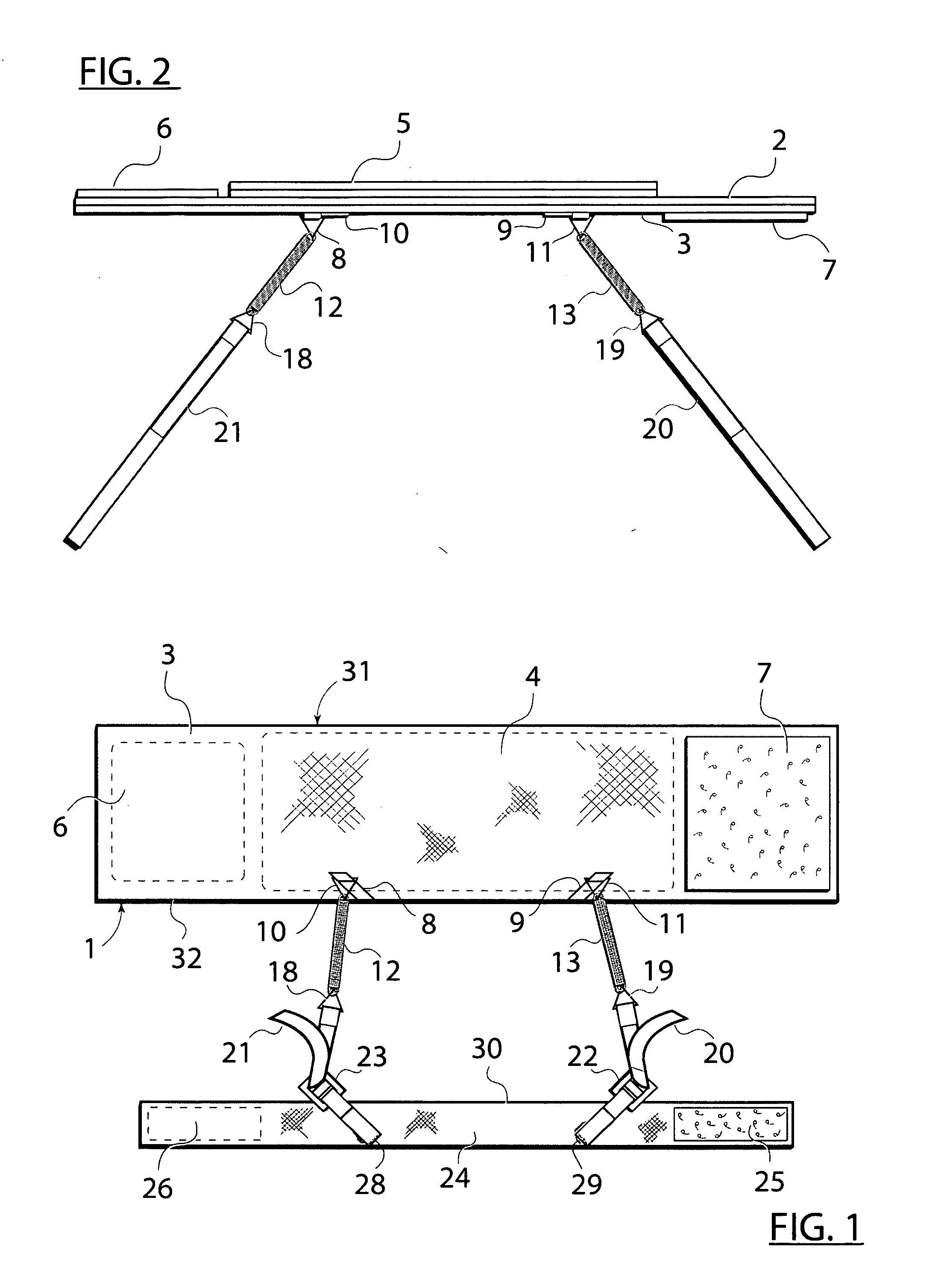
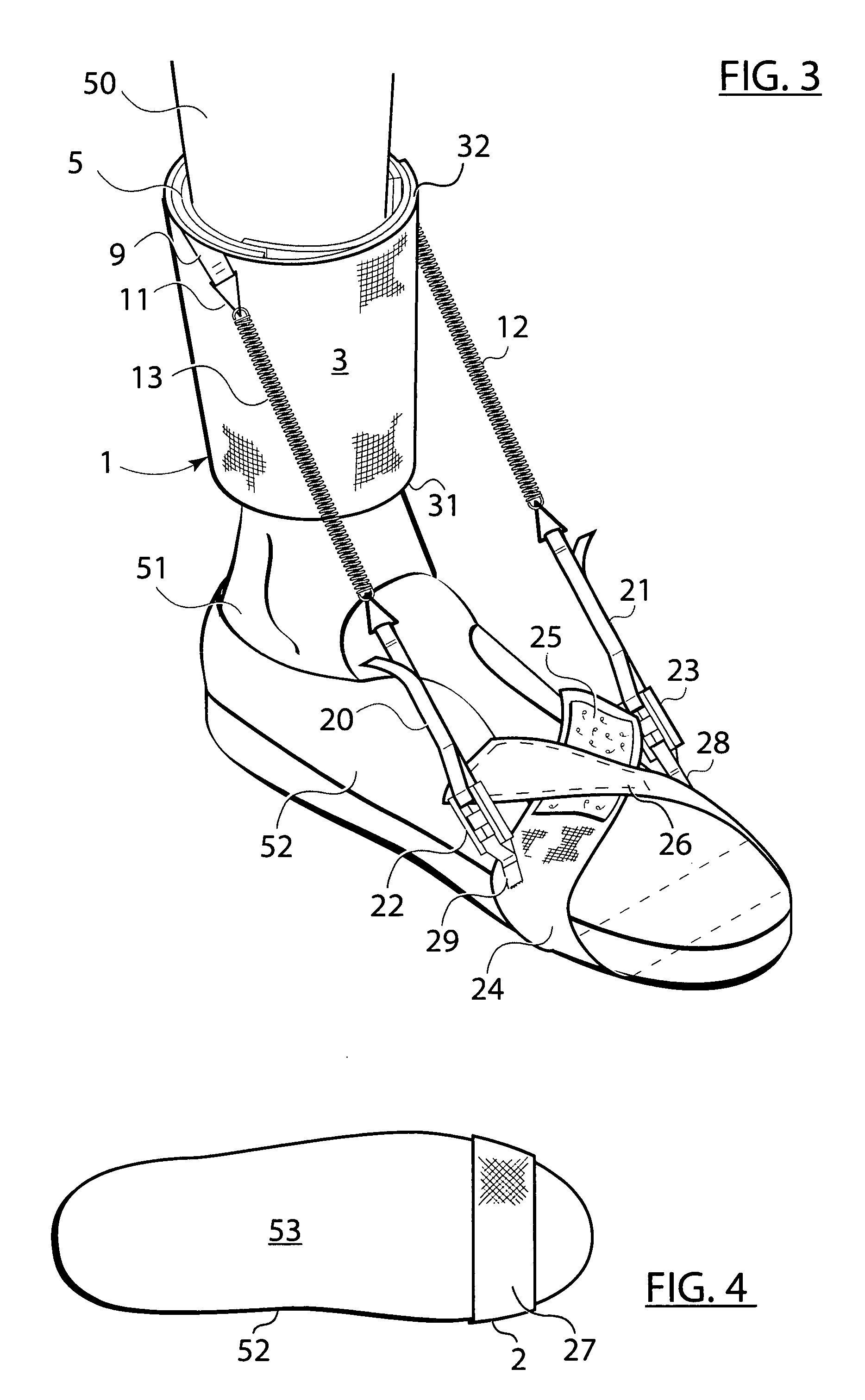
[0020]The device may be viewed as having two parts. 1) An ankle cuff with soft foam inside, two springs, each spring with an adjusting strap made up of a hook section and a loop section. 2) A foot strap with a hook section and a cooperating loop section fastener and two buckles to engage the one each of the adjusting straps on either side of the foot. Once adjusted, by moving the length of the adjusting straps equally, the user can walk with no fear of tripping.

[0021]In use the ankle belt 1 is position on the user's leg, inverted to the display in FIG. 1, such that the edge 31 is the lower edge of the ankle belt. The display in this manner provides a cleaner presentation of the components without overlaying them on the ankle belt.

[0022]FIGS. 1 and 2 show the foot drop aid (FDA). The FDA comprises an ankle belt or cuff 1, which made of a stout cloth, such as denim, of two sheets or single sheet folded over to form a pocket to provide the inner sheet 2 and the outer sheet 3. A stiffener


PUM


Abstract

An orthotic apparatus for assisting a person having an orthotic disability, such as foot drop, comprising an ankle belt component and a shoe/foot belt component connected by a pair of coil springs which are adjustably and releaseably attached between the belts. The foot at the beginning and end of the step will flex, due to the springs, and still return to lift the foot, which allows for normal walking and requires no special adaptation to the shoe.

Description


Claims


Application Information

Patent Timeline
Owner KILLIAN JAMES DR
Why Eureka
Try Eureka