Valve timing control apparatus

a timing control and valve technology, applied in mechanical equipment, valve arrangements, machines/engines, etc., can solve the problems of timing delay of control of the rotational phase of the valve timing control apparatus, abnormal sound generation, and wear of the bracket or chain

Inactive Publication Date: 2011-07-14
AISIN SEIKI KK
View PDF8 Cites 8 Cited by
  • Summary
  • Abstract
  • Description
  • Claims
  • Application Information

AI Technical Summary

Benefits of technology

This patented describes how a mechanism called a valvelocity controller can help regulate when certain parts (such as gears) are moving smoothly). It uses two types of movements - one slows down while another speeds up slowly. These movement cause friction on these components, causing them wear out faster than usual over time. To solve this problem, it suggests adding lubrication during use period instead of just keeping everything dry inside.

Problems solved by technology

This technical problem addressed in this patents relates to improving the performance and lifespan of a valvelser mechanism controller without compromising its effectiveness due to wear caused during use over longer periods of time.

Method used


Image

  • Valve timing control apparatus
  • Valve timing control apparatus
  • Valve timing control apparatus

Examples


Embodiment Construction

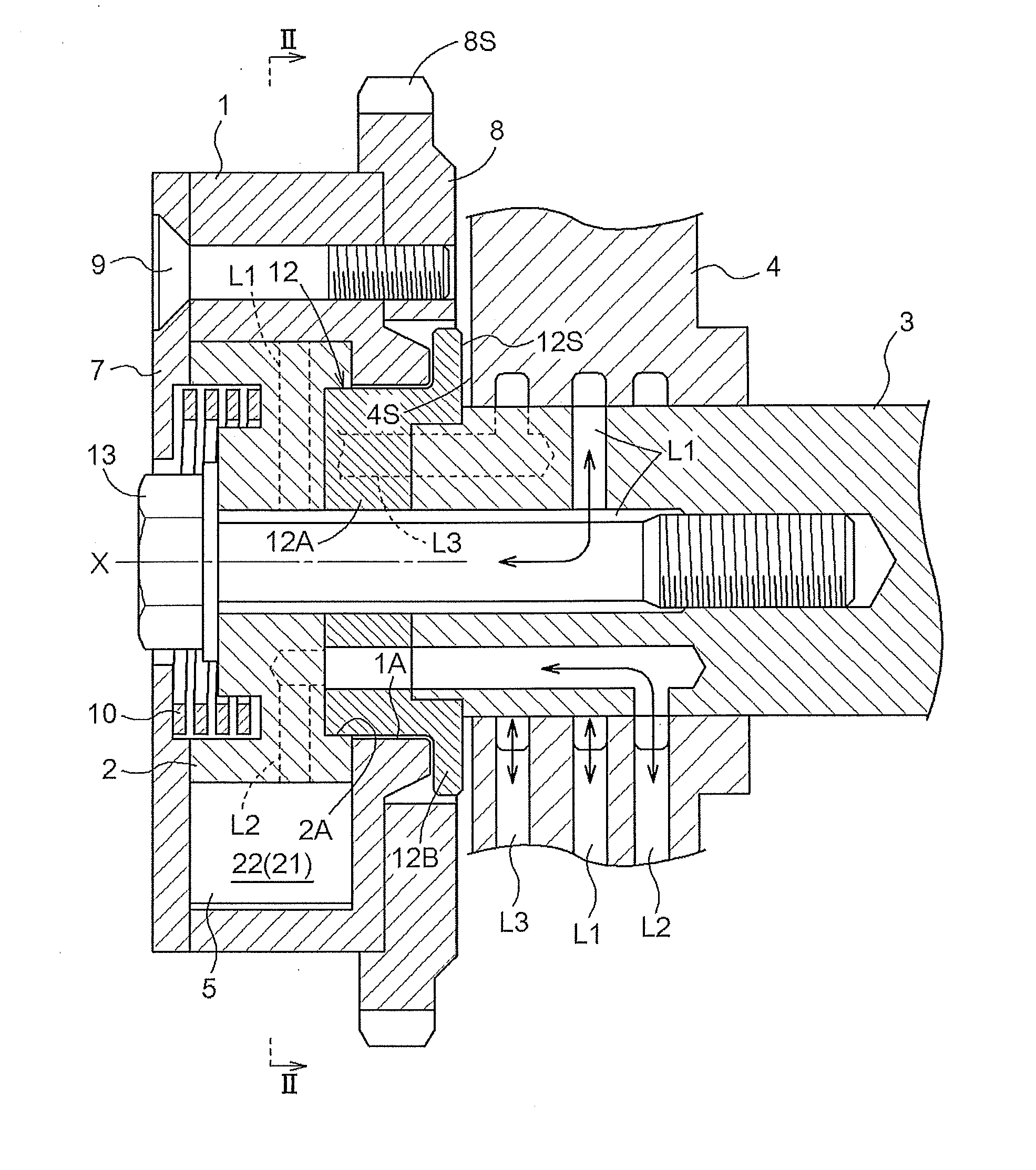
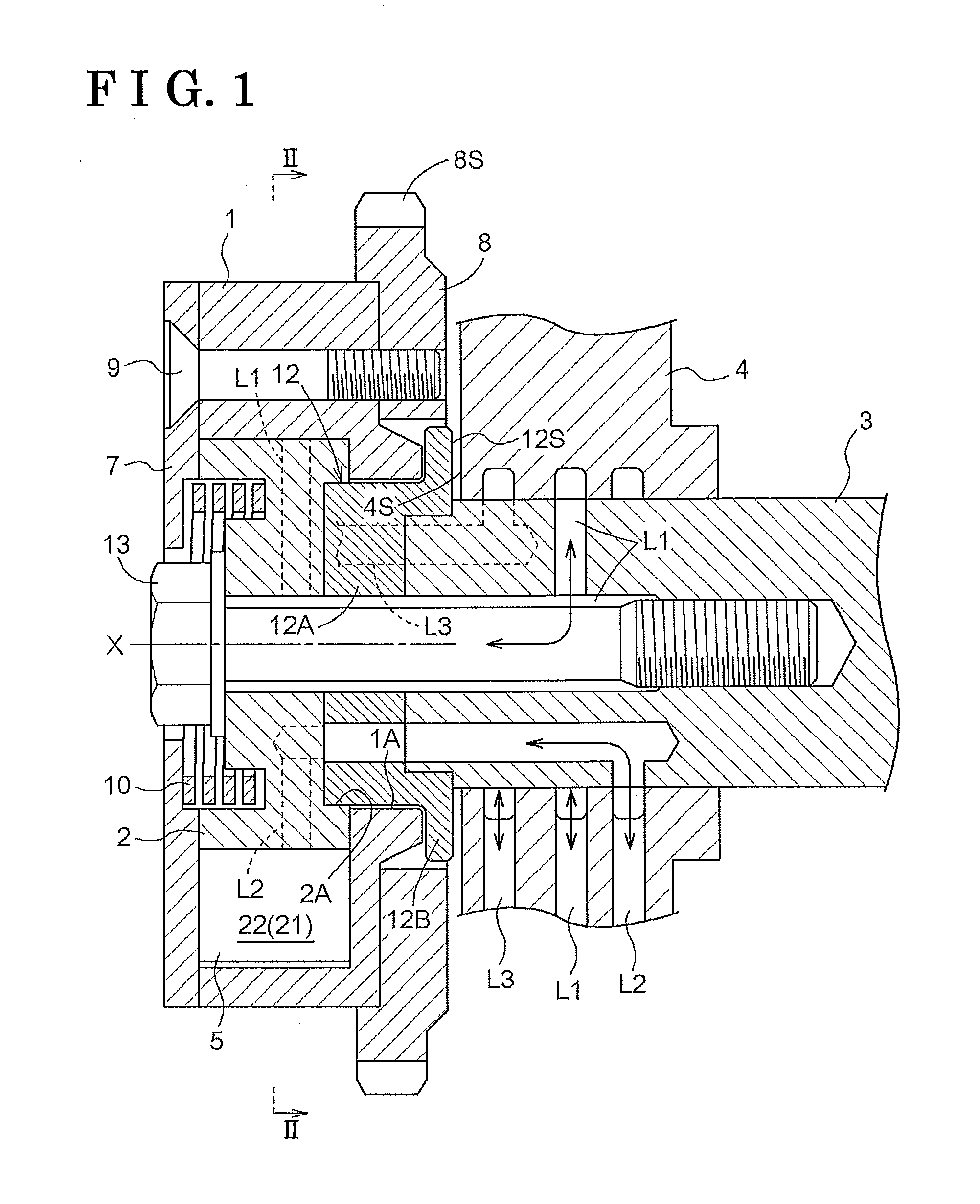
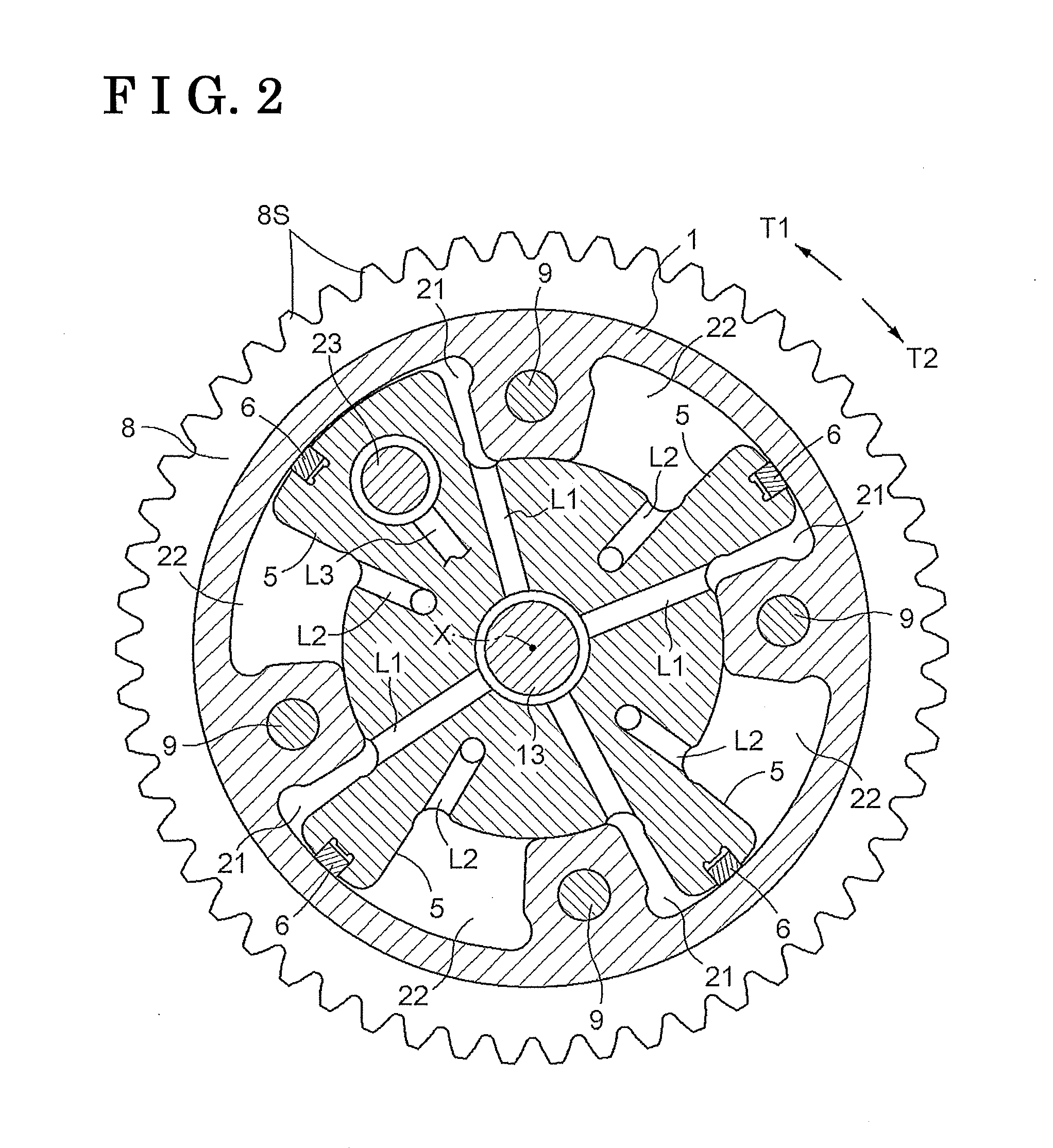
An embodiment disclosed here will be explained with reference to the attached drawings. As illustrated in FIGS. 1 and 2, a valve timing control apparatus according to the present embodiment includes an outer rotor 1 serving as a drive-side rotation member, an inner rotor 2 serving as a driven-side rotation member, retarded angle chambers 21, and advanced angle chambers 22. The retarded angle chambers 21 and the advanced angle chambers 22 constitute and serve as a rotational phase adjusting device for changing or adjusting a relative rotational phase between the outer rotor 1 and the inner rotor 2 by supply and discharge of an operation oil relative to either the retarded angle chambers 21 or the advanced angle chambers 22 from an electromagnetic control valve. The outer rotor 1 synchronously rotates with a crankshaft of an engine (i.e., an internal combustion engine) via a timing chain. The inner rotor 2 integrally rotates with a camshaft 3 that opens or closes an intake valve or an ex


PUM


Abstract

A valve timing control apparatus includes a drive-side rotation member synchronously rotating with a crankshaft of an internal combustion engine, a driven-side rotation member integrally rotating with a camshaft, a rotational phase adjusting device including a retarded angle chamber and an advanced angle chamber, the rotational phase adjusting device adjusting the relative rotational phase between the drive-side rotation member and the driven-side rotation member, and a boss member provided at a portion of the driven-side rotation member facing an outer wall surface of the internal combustion engine and including a thrust surface that extends to be perpendicular to a rotational axis of the camshaft and that is exposed to the outer wall surface of the internal combustion engine. The boss member causes the drive-side rotation member to be prevented from making contact with the outer wall surface by making contact with the outer wall surface of the internal combustion engine.

Description


Claims


Application Information

Patent Timeline
Owner AISIN SEIKI KK
Why Eureka
Try Eureka