Method and apparatus for implementing variable symbol rate

a symbol rate and variable technology, applied in the field of signal modulation technology, can solve the problems of high cost and high price of clock adjustable chips, and achieve the effects of stable performance, low cost of fpga, and low cost of the present invention

Inactive Publication Date: 2011-11-17
SHENZHEN COSHIP ELECTRONICS CO LTD
View PDF3 Cites 1 Cited by
  • Summary
  • Abstract
  • Description
  • Claims
  • Application Information

AI Technical Summary

Benefits of technology

The present invention provides a way to control the timing of symbols that are sent over communication networks. It achieves this by controlling how long each symbol takes to go before being received at its destination. This allows for more precise synchronization between different devices connected to the network. By adjusting certain parameters or changing the order of data transmission based on specific needs, the device's ability to accurately transmit signals without any issues like signal interference or distortion may also improve their overall performance. Overall, this technology helps ensure reliable communication across various types of networks while reducing costs associated with traditional methods such as time division multiplexed (TDM) and error correction codes.

Problems solved by technology

This patent describes a problem with existing modulators that have a constant speed capability due to their ability to generate different types of symbols per second. These modulators require expensive components like transistors or integrated circuits, leading to increased costs and reduced efficiency. Additionally, these modulators cannot achieve both fast and slow response times simultaneously, resulting in slower processing time.

Method used


Image

  • Method and apparatus for implementing variable symbol rate
  • Method and apparatus for implementing variable symbol rate
  • Method and apparatus for implementing variable symbol rate

Examples


Embodiment Construction

[0048]For the objectives, features, and advantages of the present invention being better understood and legibly, the present invention will now be described more specifically with reference to the drawings and accompanying embodiments are particularized.

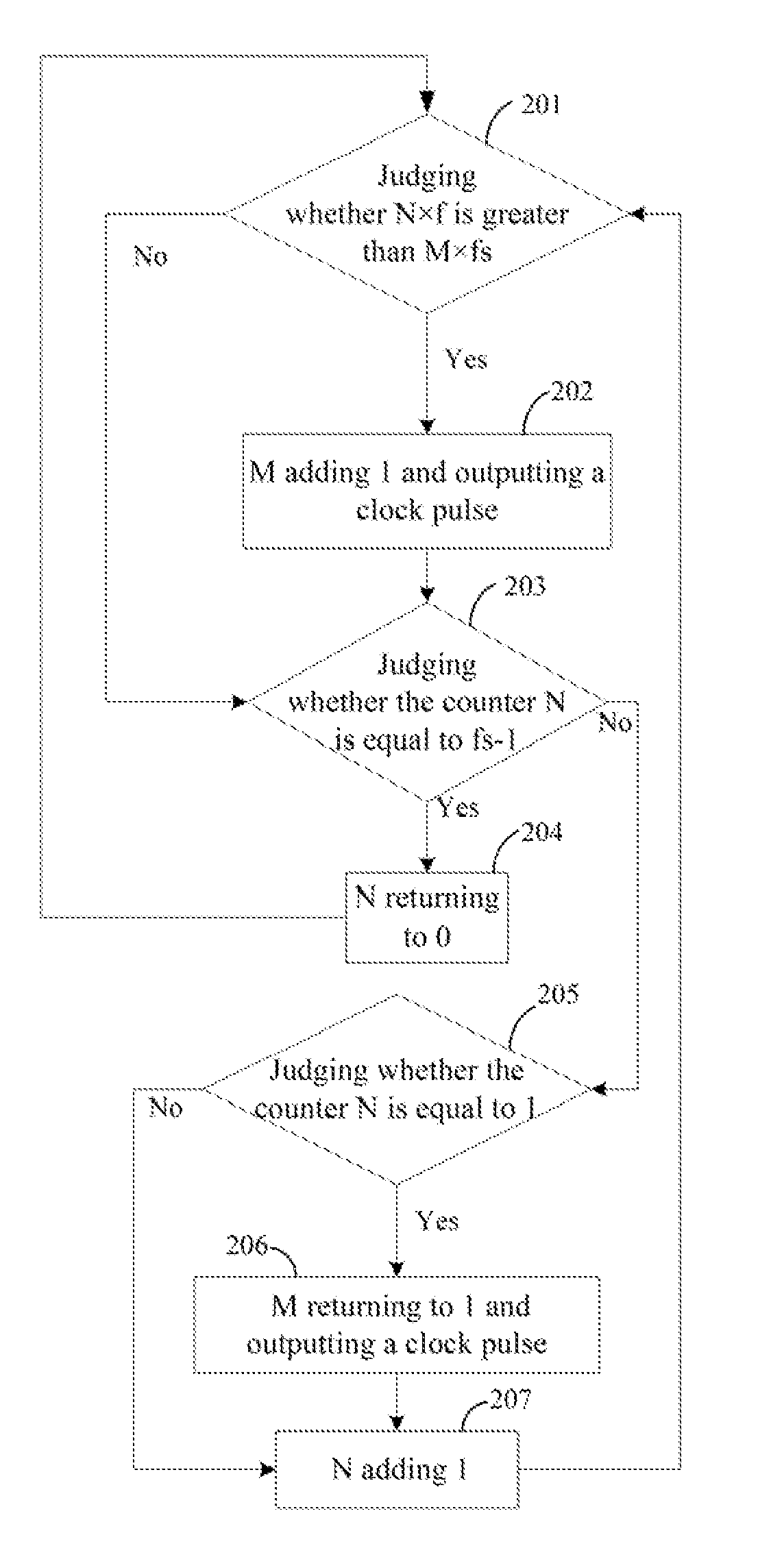
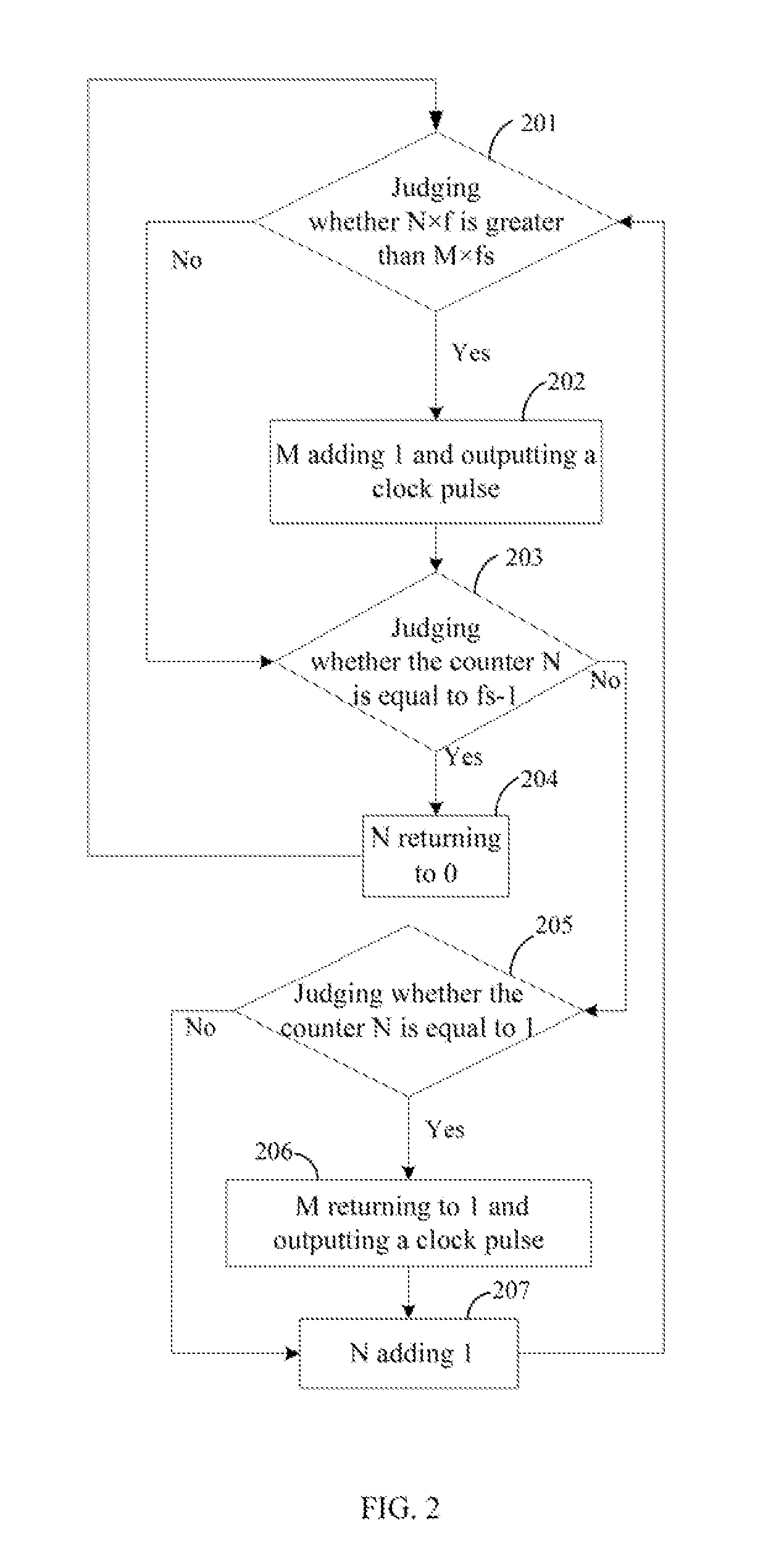
[0049]In the embodiment, a method for implementing variable symbol rate is provided. The detailed implement process of the method is shown in FIG. 2, wherein the method includes:

[0050]Step 201: Judging whether N×f is greater than M×fs at the rising edge of outside input clock, if N×f is greater than M×fs, the process continues by going to step 202, else the process goes to step 203, wherein, setting the original value of the counter M to 1, the original value of the counter N is 0;

[0051]Step 202: The counter M adding 1 and outputting a clock pulse, further the process goes to step 203;

[0052]Step 203: Judging whether the counter N is equal to fs−1, if it is, the process goes to step 204, else the process goes to step 205;

[0053]Step 204:


PUM


Abstract

A method for implementing variable symbol rate, presetting counters M and N, and M=1, N=0, f being the preset output symbol rate, fs being the frequency of input clock, the method comprises: triggering to judge whether N×f is greater than M×fs at the rising edge of the input clock, if it is, letting the counter M add 1 and outputting a clock pulse; else further judging whether the value of the counter N is equal to fs−1; when N=fs−1, letting the counter N return to 0, and waiting for the next rising edge of the input clock; when N≠fs−1, waiting for the next rising edge of the input clock after letting the counter N add 1; letting the output clock pulse be the system clock, controlling the data to be output to set the symbol rate output.

Description


Claims


Application Information

Patent Timeline
Owner SHENZHEN COSHIP ELECTRONICS CO LTD
Why Eureka
Try Eureka