Imprinting apparatus and imprinting method using the same

a technology of imprinting apparatus and imprinting process, which is applied in the direction of electrical/magnetic/electromagnetic heating, instruments, applications, etc., can solve the problems of blurs on the substrate with patterns, increase of manufacturing cost of the imprinting process, and deterioration of picture quality of images displayed on the display device, so as to facilitate the formation of patterns

Inactive Publication Date: 2011-12-08
LG DISPLAY CO LTD
View PDF4 Cites 8 Cited by
  • Summary
  • Abstract
  • Description
  • Claims
  • Application Information

AI Technical Summary

Benefits of technology

The technical effect of this patented technology allows for better control over how patterns are formed during printing compared with traditional methods that require a specialized surface or platform.

Problems solved by technology

This patented technical solution described involves creating patterns onto surfaces during the production of displays like liquid crystals or organic light emitting diodes (OLEDS). These techniques involve applying pressure to the surface while it forms certain shapes that correspond to those needed for forming them. However, there can be issues where some areas get covered up when trying to make sure they don't become visible even if only slightly uneven. Blurriness also occurs over time because the printed area becomes more pronounced at higher temperatures than other parts of the panel. Additionally, current methods require expensive equipment which increases costs compared to lower pricing options.

Method used


Image

  • Imprinting apparatus and imprinting method using the same
  • Imprinting apparatus and imprinting method using the same
  • Imprinting apparatus and imprinting method using the same

Examples


Embodiment Construction

[0020]Reference will now be made in detail to the exemplary embodiments of the present invention, examples of which are illustrated in the accompanying drawings. Wherever possible, the same reference numbers will be used throughout the drawings to refer to the same or like parts.

[0021]Hereinafter, an imprinting apparatus according to the present invention will be described with reference to the accompanying drawings.

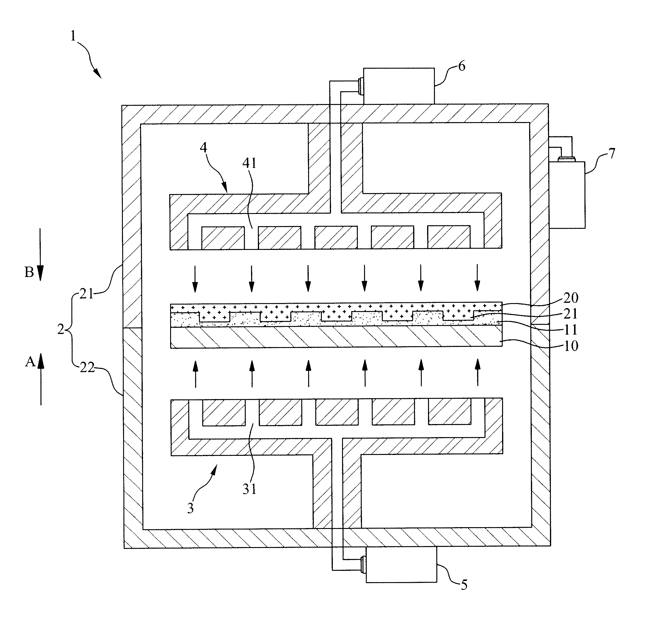
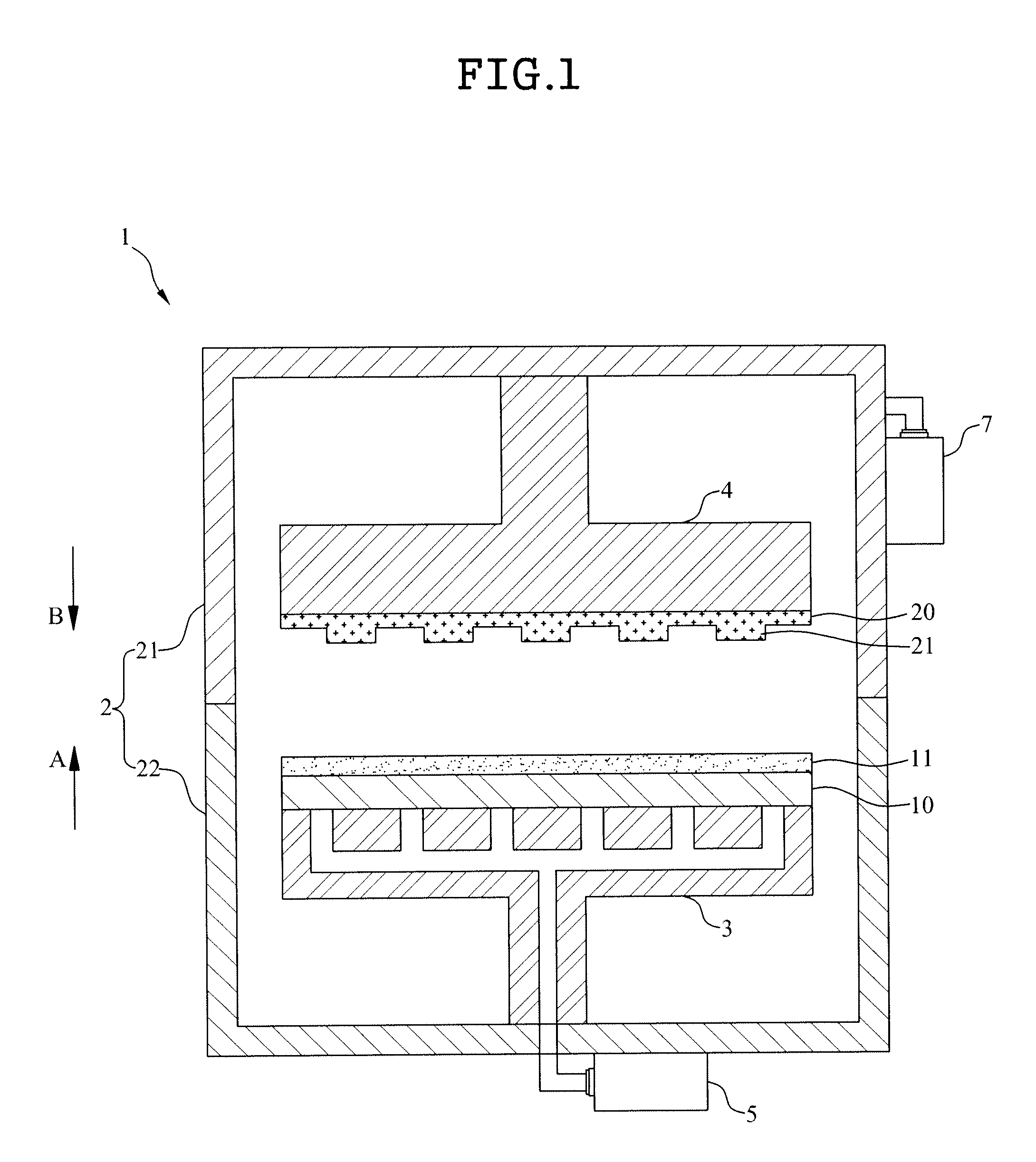
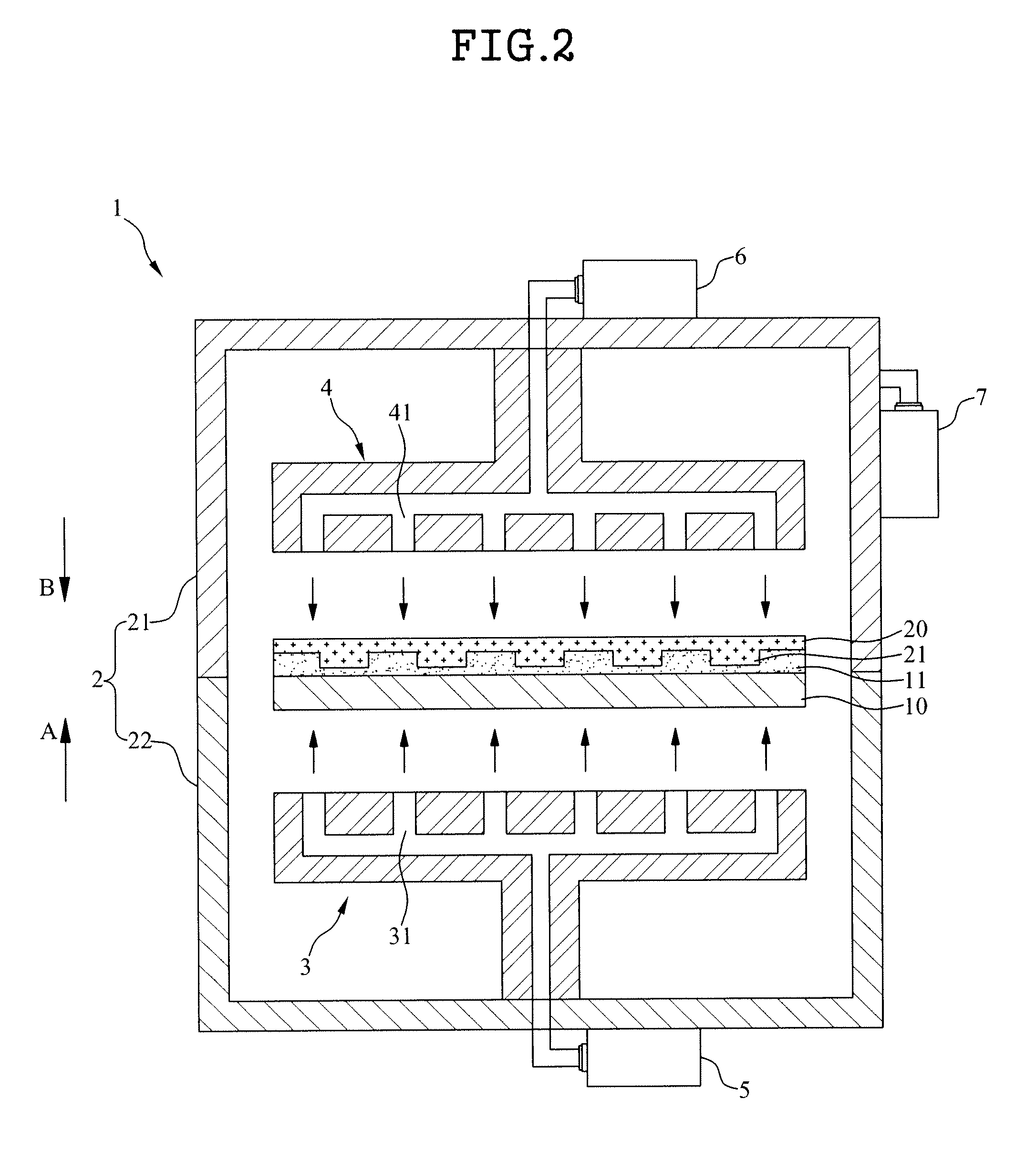
[0022]FIG. 1 is a cross section view illustrating an imprinting apparatus according to the present invention. FIG. 2 is a cross section view illustrating an operational relationship in an imprinting apparatus according to the present invention. FIGS. 3 and 4 are plane views illustrating a stage according to the present invention. FIG. 5 is a cross section view illustrating an imprinting apparatus according to a modified embodiment of the present invention.

[0023]Referring to FIG. 1, the imprinting apparatus 1 according to the present invention includes a chamber unit 2; a st


PUM

PropertyMeasurementUnit
Pressureaaaaaaaaaa
Shapeaaaaaaaaaa

Abstract

Disclosed is an imprinting apparatus and imprinting method using the same that prevent a process of forming a pattern on a substrate from being affected by flatness of a stage. The imprinting apparatus comprises a chamber unit in which a process of forming a pattern on a substrate is carried out; a stage for supporting the substrate on which a resin layer is formed; an installing member positioned above the stage and having a mold member attached to transform the resin layer so as to form the pattern on the substrate; and a first spraying unit for spraying fluid to separate the substrate supported by the stage from the stage, wherein the installing member moves the mold member in the direction getting near to the substrate separated from the stage so that the mold member and the resin layer are brought into contact with each other.

Description


Claims


Application Information

Patent Timeline
Owner LG DISPLAY CO LTD
Why Eureka
Try Eureka