Coupled acoustic devices

a technology of coupled acoustic devices and acoustic waves, which is applied in the direction of impedence networks, electrical devices, etc., can solve the problems of filtering that cannot meet the bandwidth requirements, the bandwidth is too narrow, and the insertion loss is high, so as to achieve the effect of widening the band width and reducing the ripple of the pass band

Active Publication Date: 2012-01-12
PANG WEI +1
View PDF4 Cites 35 Cited by
  • Summary
  • Abstract
  • Description
  • Claims
  • Application Information

AI Technical Summary

Benefits of technology

The invention relates an audio device that matches different types of electrical components with each other's characteristics such as resistance values. This helps improve sound quality by reducing unwanted sounds caused when transmitting signals through electronic devices like speakers.

Problems solved by technology

This patented technical problem addressed in this patents relates to improving the quality of electronic components made up of different materials due to their unique properties. Specifically, these materials have limitations related to how well they work together for achieving desired functions like sound generation. To solve them, researchers developed techniques involving combining certain elements into multilayer structures containing interdigitated conductors placed next to each other. By doing this, energy generated through vibrational excitation becomes distributed evenly across all dielectrics while minimizing any unwanted responses caused by nonlinearities. However, previous methods were unable to effectively reduce noise levels associated with FBAs without sacrificial insulation layers.

Method used


Image

  • Coupled acoustic devices
  • Coupled acoustic devices
  • Coupled acoustic devices

Examples


Embodiment Construction

[0045]The present invention will now be described more fully hereinafter with reference to the accompanying drawings, in which exemplary embodiments of the invention are shown. This invention may, however, be embodied in many different forms and should not be construed as limited to the embodiments set forth herein. Rather, these embodiments are provided so that this disclosure will be thorough and complete, and will fully convey the scope of the invention to those skilled in the art. Like reference numerals refer to like elements throughout.

[0046]It will be understood that when an element is referred to as being “on” another element, it can be directly on the other element or intervening elements may be present therebetween. In contrast, when an element is referred to as being “directly on” another element, there are no intervening elements present. As used herein, the term “and / or” includes any and all combinations of one or more of the associated listed items.

[0047]It will be unde


PUM


Abstract

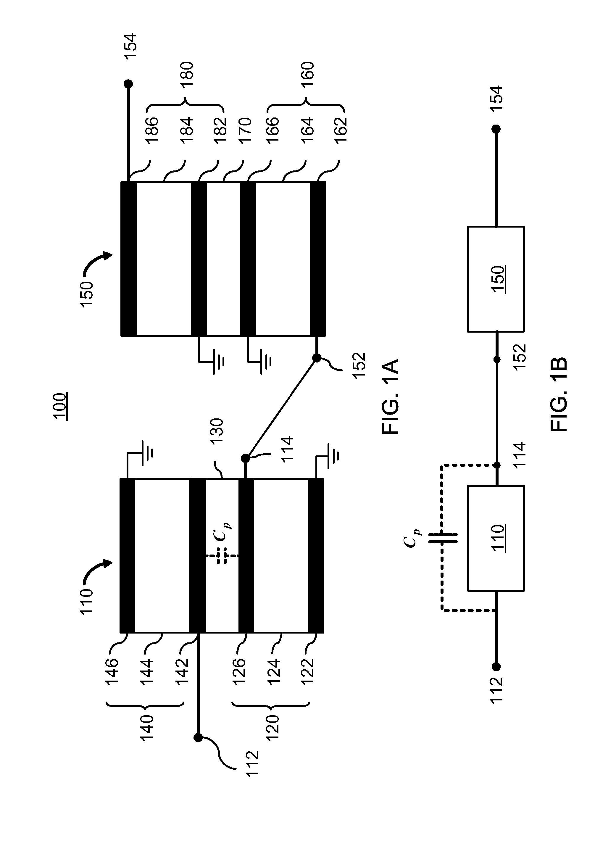
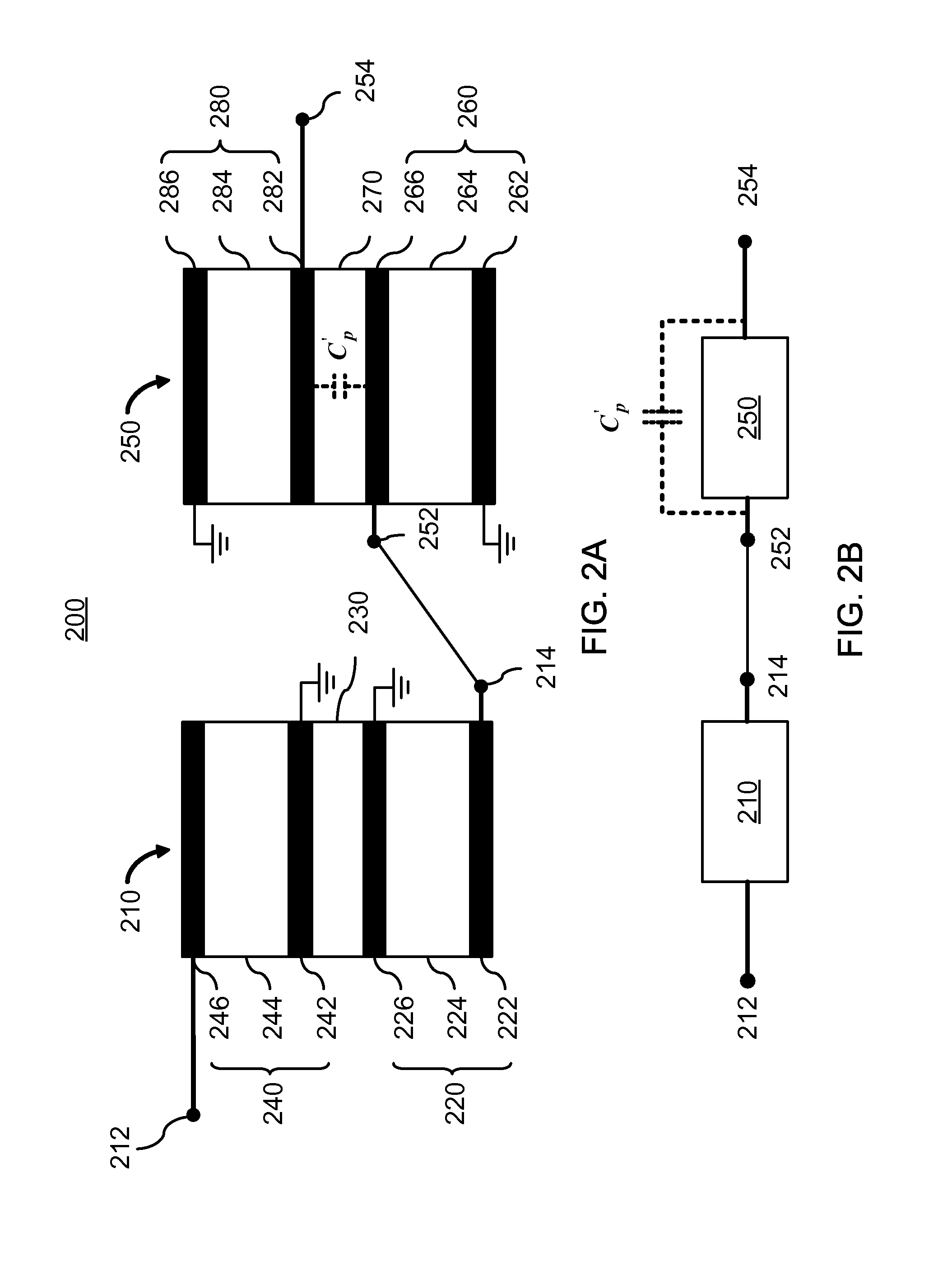
In one aspect of the invention, an acoustic device has a first coupled resonator filter (CRF) and a second CRF electrically coupled to one another in series. Each CRF has an input port, an output port, a bottom film bulk acoustic resonator (FBAR), an acoustic decoupler formed on the bottom FBAR, and a top FBAR formed on the acoustic decoupler. Each FBAR has a bottom electrode, a piezoelectric layer formed on the bottom electrode, and a top electrode formed on the piezoelectric layer. The decoupling layer capacitance arising between the two electrodes enclosing the acoustic decoupler in a CRF is configured to achieve targeted filter response. A compensating capacitance is introduced to improve the amplitude and phase imbalance performance of an unbalanced to balanced CRF by eliminating the existence of asymmetric port-to-ground or feedback capacitance at the balanced output port produced by the decoupling layer capacitance.

Description


Claims


Application Information

Patent Timeline
Owner PANG WEI
Why Eureka
Try Eureka