Thermal head and method of manufacturing the same, and printer
a manufacturing method and thermal head technology, applied in printing and other directions, can solve the problems of insufficient utilization of high heat insulation performance of the cavity portion, reduced thermal efficiency of the thermal head, etc., and achieve the effect of improving thermal efficiency, reducing the amount of energy required for printing, and increasing thermal efficiency
- Summary
- Abstract
- Description
- Claims
- Application Information
AI Technical Summary
Benefits of technology
Problems solved by technology
Method used
Image


Examples
first embodiment
[0043]A thermal head 1 and a thermal printer 10 according to a first embodiment of the present invention are described below with reference to the accompanying drawings.
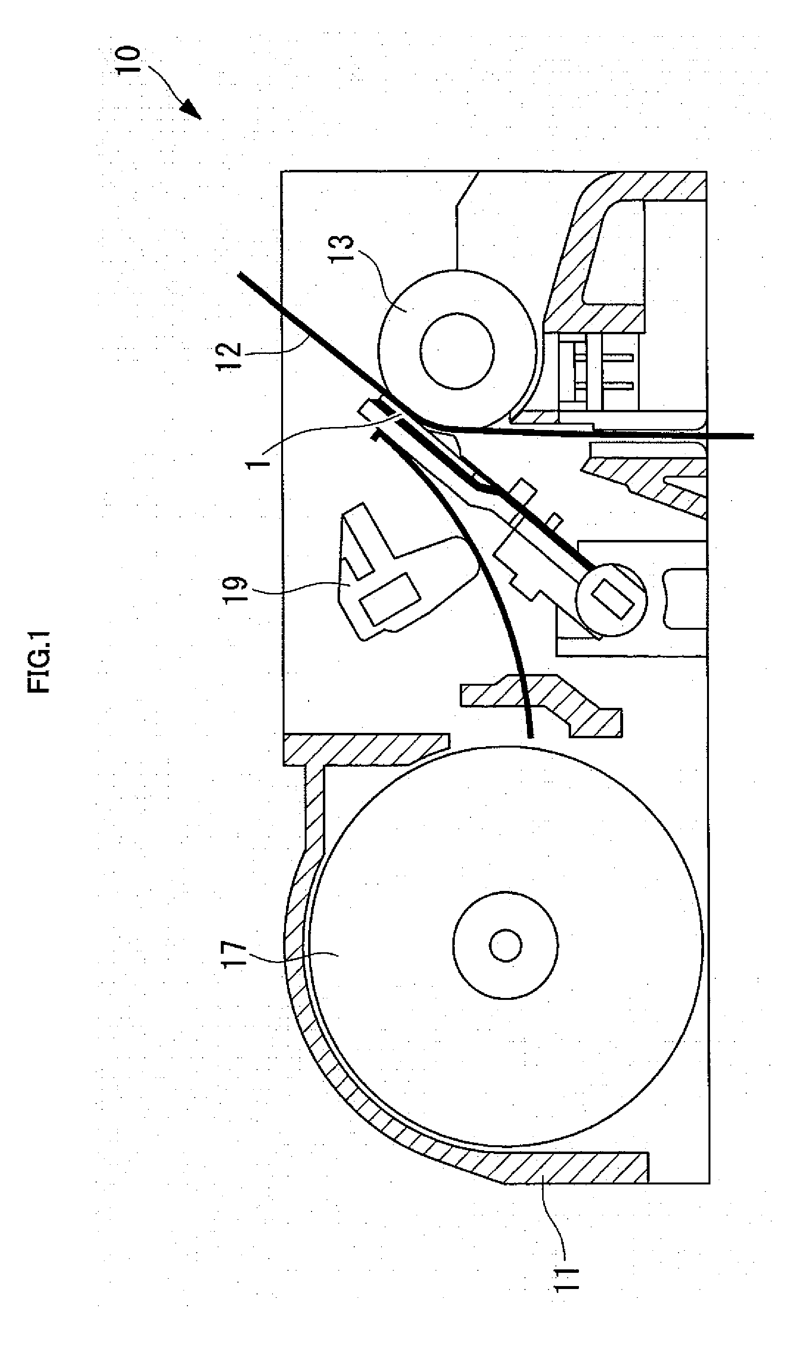
[0044]The thermal head 1 according to this embodiment is used for, for example, the thermal printer 10 as illustrated in FIG. 1, and performs printing on an object to be printed, such as thermal paper 12, by selectively driving a plurality of heating elements based on printing data.
[0045]The thermal printer 10 includes a main body frame 11, a platen roller 13 disposed with its central axis being horizontal, the thermal head 1 disposed opposite to an outer peripheral surface of the platen roller 13, a heat dissipation plate (not shown) supporting the thermal head 1, a paper feeding mechanism 17 for feeding the thermal paper 12 between the platen roller 13 and the thermal head 1, and a pressure mechanism 19 for pressing the thermal head 1 against the thermal paper 12 with a predetermined pressing force.
[0046]Against the p
first modified example
[0084]A first modified example of the thermal head 1 according to this embodiment is described below. Note that, the description common to the above-mentioned thermal head 1 according to the first embodiment is omitted below, and hence the following description is mainly directed to differences.
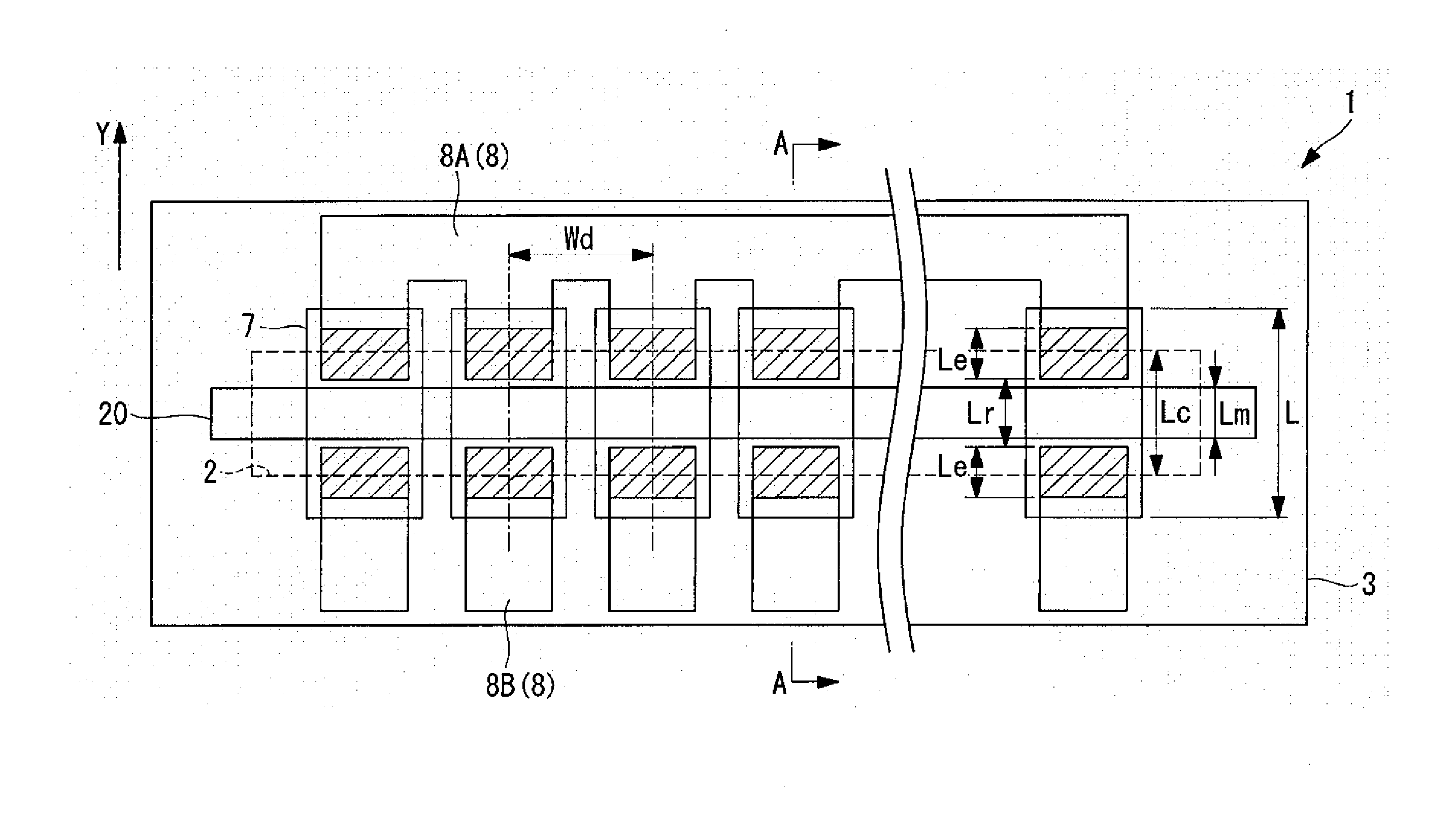
[0085]In the thermal head 1 according to the first embodiment, as illustrated in FIG. 3, the thin portion 18 of the electrode 8 is disposed in the range of from the inside of the region on the heating resistor 7 corresponding to the concave portion 2 to the outside of the region. In contrast, in a thermal head 41 according to this modified example, as illustrated in FIG. 5, the thin portion 18 of the electrode 8 is formed inside the region on the heating resistor 7 corresponding to the concave portion 2. In other words, in the thermal head 41 according to this modified example, the thick portion 16 is also formed inside the region on the heating resistor 7 corresponding to the concave portion 2.
second modified example
[0087]A second modified example of the thermal head 1 according to this embodiment is described below.
[0088]In the thermal head 1 according to the first embodiment, as illustrated in FIG. 3, the electrode 8 is formed of a two-stage structure including the thin portion 18 and the thick portion 16. In contrast, in a thermal head 42 according to this modified example, as illustrated in FIG. 6, the electrode 8 in the vicinity of the heating resistor 7 is formed of a three-stage structure including the thin portion 18, an intermediate portion 17, and the thick portion 16.
[0089]With such a structure, the thermal efficiency of the entire thermal head may be optimized considering a balance between the heat dissipation amount via the thick portion 16 of the electrode 8 and the electrical resistance value of the electrode 8 (heating efficiency of the heating resistor 7). Further, the intermediate portion 17 is provided, and hence the step of the electrode 8 may be reduced to improve the formatio
PUM
 Abstract
Description
Claims
Application Information
 - R&D Engineer
- R&D Manager
- IP Professional
- Industry Leading Data Capabilities
- Powerful AI technology
- Patent DNA Extraction
Browse by: Latest US Patents, China's latest patents, Technical Efficacy Thesaurus, Application Domain, Technology Topic.
© 2024 PatSnap. All rights reserved.Legal|Privacy policy|Modern Slavery Act Transparency Statement|Sitemap