Display device

Active Publication Date: 2013-03-14
SATURN LICENSING LLC
View PDF14 Cites 6 Cited by
  • Summary
  • Abstract
  • Description
  • Claims
  • Application Information

AI Technical Summary

Benefits of technology

[0033]According to the present invention, it is possible to provide an excellent display device that can display both two-dimensional images and three-dimensional images, suppressing the generation of crosstalk when displaying a three-dimensional image while avoiding a decrease in brightness when displaying a two-dimensional image.
[0034]According to the present invention, since the division of light at a boundary at which the polarization state of the polarization control filter changes is realized without a black matrix by providing a row of pixels that are constantl

Problems solved by technology

Here, with a display device using a polarization control filter, there is a problem in that the division of light is insufficient at a boundary at which the polarization state of the filter changes.
However, if a black matrix is arranged at a boundary portion in which the polarization state of the polarization control filter changes, there is a problem in that the b

Method used


Image

  • Display device
  • Display device
  • Display device

Examples


Embodiment Construction

[0053]Embodiments of the present invention will be described in detail below with reference to the drawings.

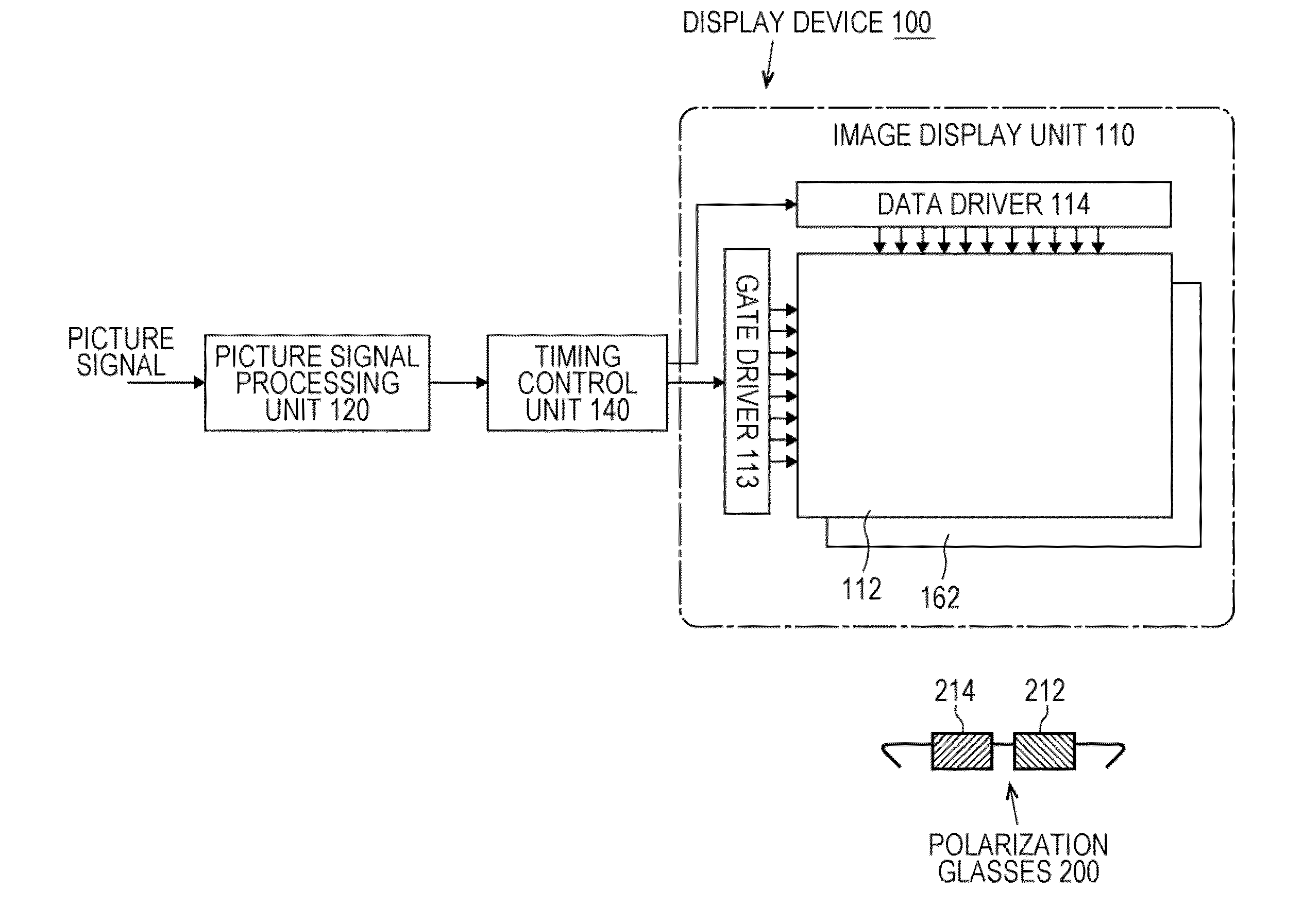
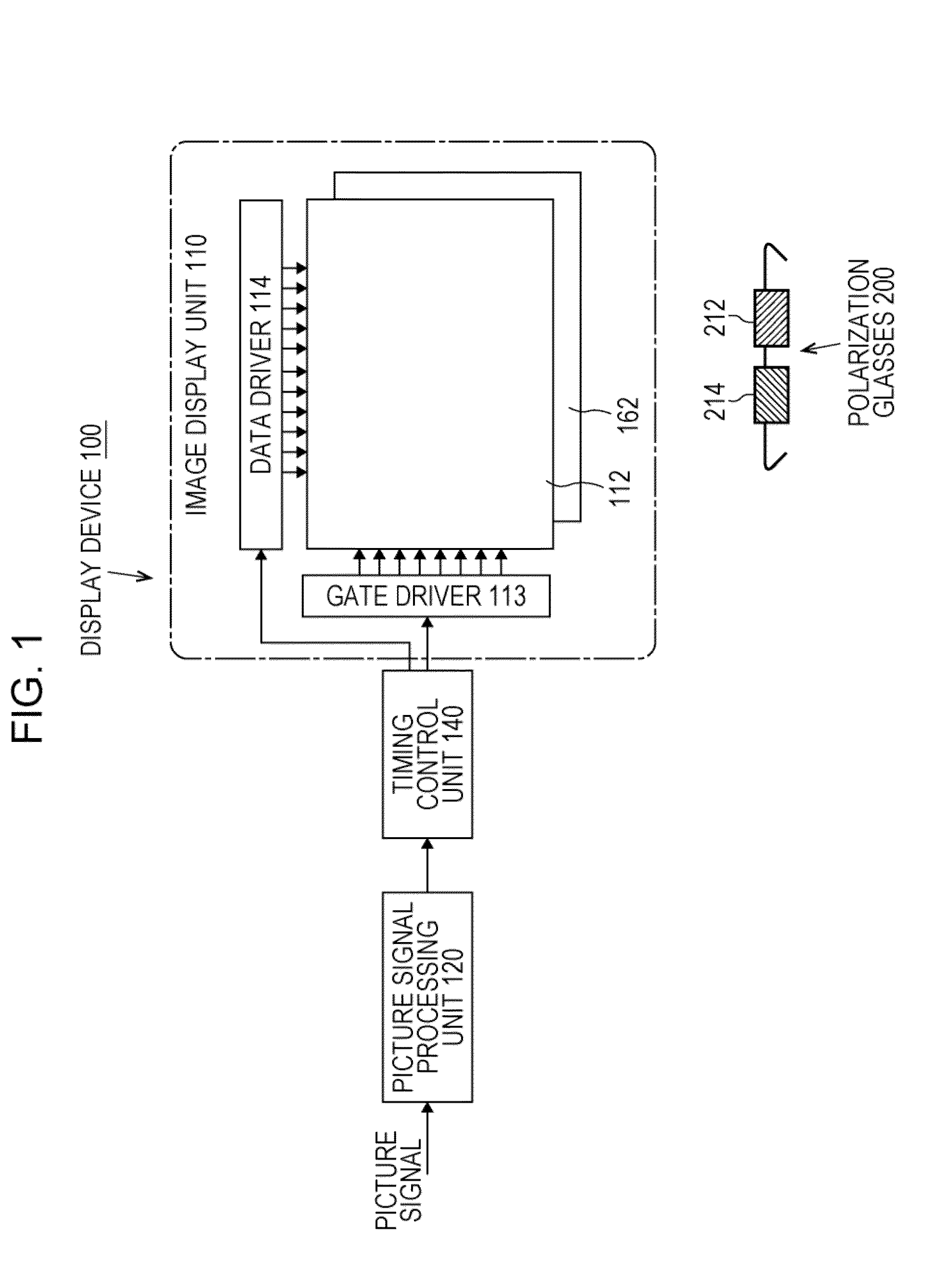
[0054]The functional configuration of a display device 100 displaying both two-dimensional images and three-dimensional images is schematically illustrated in FIG. 1. Further, polarization glasses 200 for the viewer to perceive an image that the display device 100 displays as a stereoscopic image is also illustrated in FIG. 1.

[0055]The display device 100 includes an image display unit 110, a picture signal control unit 120, and a timing control unit 140.

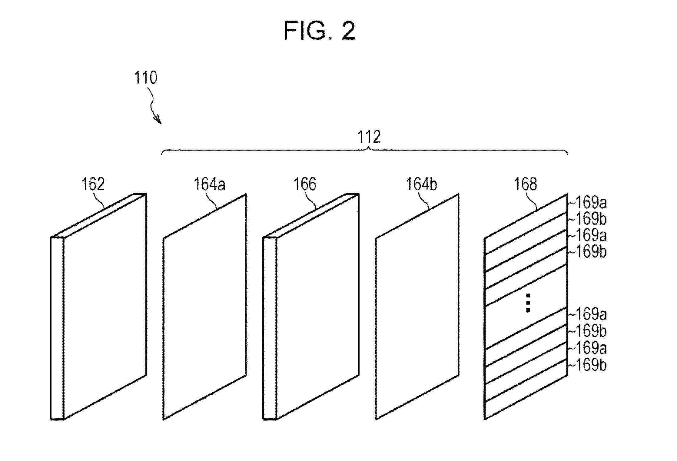
[0056]The image display unit 110 performs the display of an image according to a signal applied from the outside. The image display unit 110 includes a display panel 112, a gate driver 113, a data driver 114, and a light source 162.

[0057]Liquid crystal molecules with a predetermined orientation state are enclosed between transparent plates such as glass in the display panel 112, which displays an image according to the application


PUM


Abstract

The generation of crosstalk is suppressed when displaying a three-dimensional image, and a decrease in brightness is avoided when displaying a two-dimensional image.
A polarization control filter 268 is placed so that a boundary between a polarization region 269a and a polarization region 269b is within the ranges of a red liquid crystal cell 272, a green liquid crystal cell 274, and a blue liquid crystal cell 276 in order in the vertical direction. When displaying a three-dimensional image, black is displayed for a liquid crystal cell 2 positioned at a boundary between the polarization region 269a and the polarization region 269b of a polarization control filter 268, and the original right eye image or left eye image is displayed by other liquid crystal cells.

Description


Claims


Application Information

Patent Timeline
Owner SATURN LICENSING LLC
Why Eureka
Try Eureka