System and Method for Directing Energy to Tissue

a tissue and energy technology, applied in the field of systems and devices for performing medical procedures, can solve the problems of undesirable tissue damage, thermal injury to surrounding tissue, and generation of heat, so as to improve patient outcomes, improve patient safety, and reduce risk

Active Publication Date: 2013-11-14
TYCO HEALTHCARE GRP LP
View PDF9 Cites 42 Cited by
  • Summary
  • Abstract
  • Description
  • Claims
  • Application Information

AI Technical Summary

Benefits of technology

The technical effect that this invention provides solutions are improving patients' health by reducing their risks or making them better off from certain conditions.

Problems solved by technology

This patent describes various technical problem addressed within the field of medical science relating to control and measuring the temperature of body tissue affected by high intensity focused ultrasound waves generated by an apparatus used for electrasonics therapy. Current solutions involve applying direct currents to the target area while simultanously supplying alternated voltages to generate specific levels of heat without causing unwanted side effects. However, these approaches have limitations because they cannot measure the actual physical properties of the region being operated upon effectively. Additionally, existing feedback mechanisms lack precision and accuracy, making them difficult to implement accurately.

Method used


Image

  • System and Method for Directing Energy to Tissue
  • System and Method for Directing Energy to Tissue
  • System and Method for Directing Energy to Tissue

Examples


Embodiment Construction

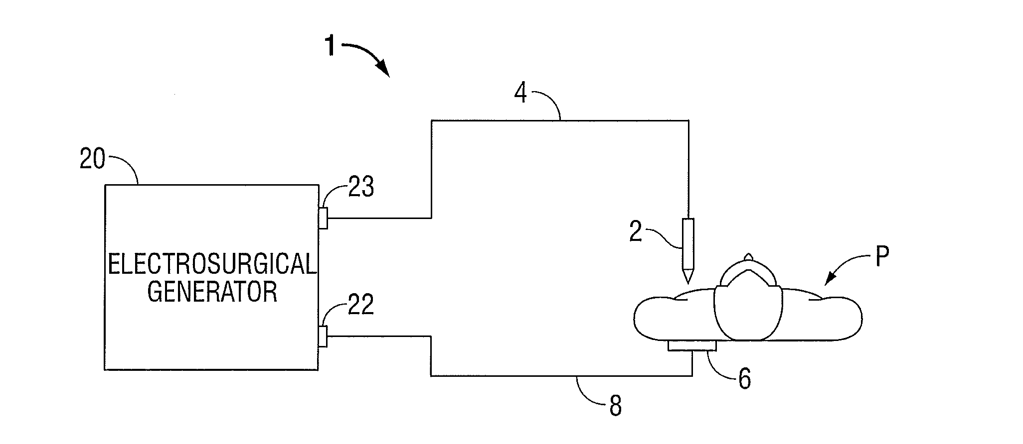
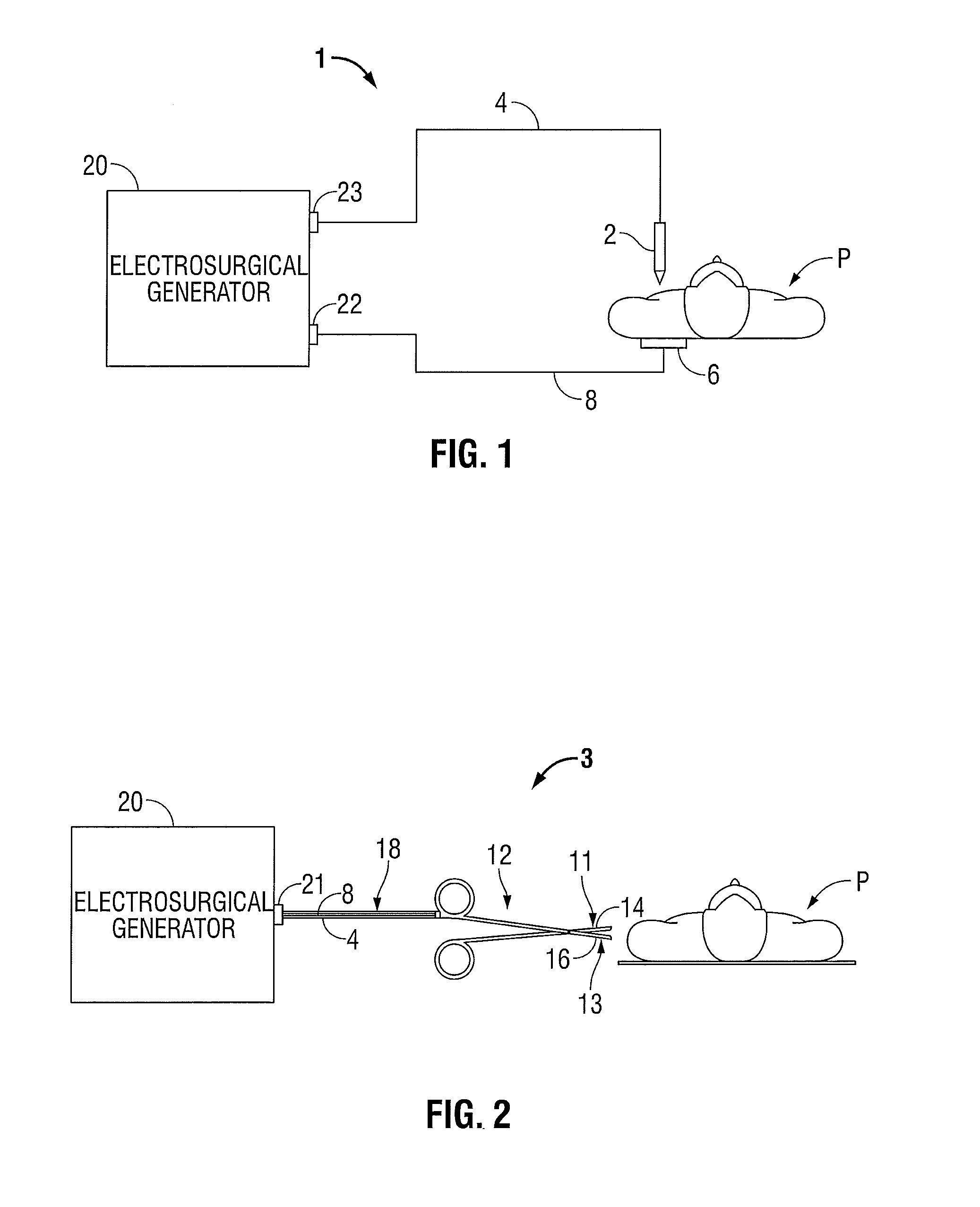
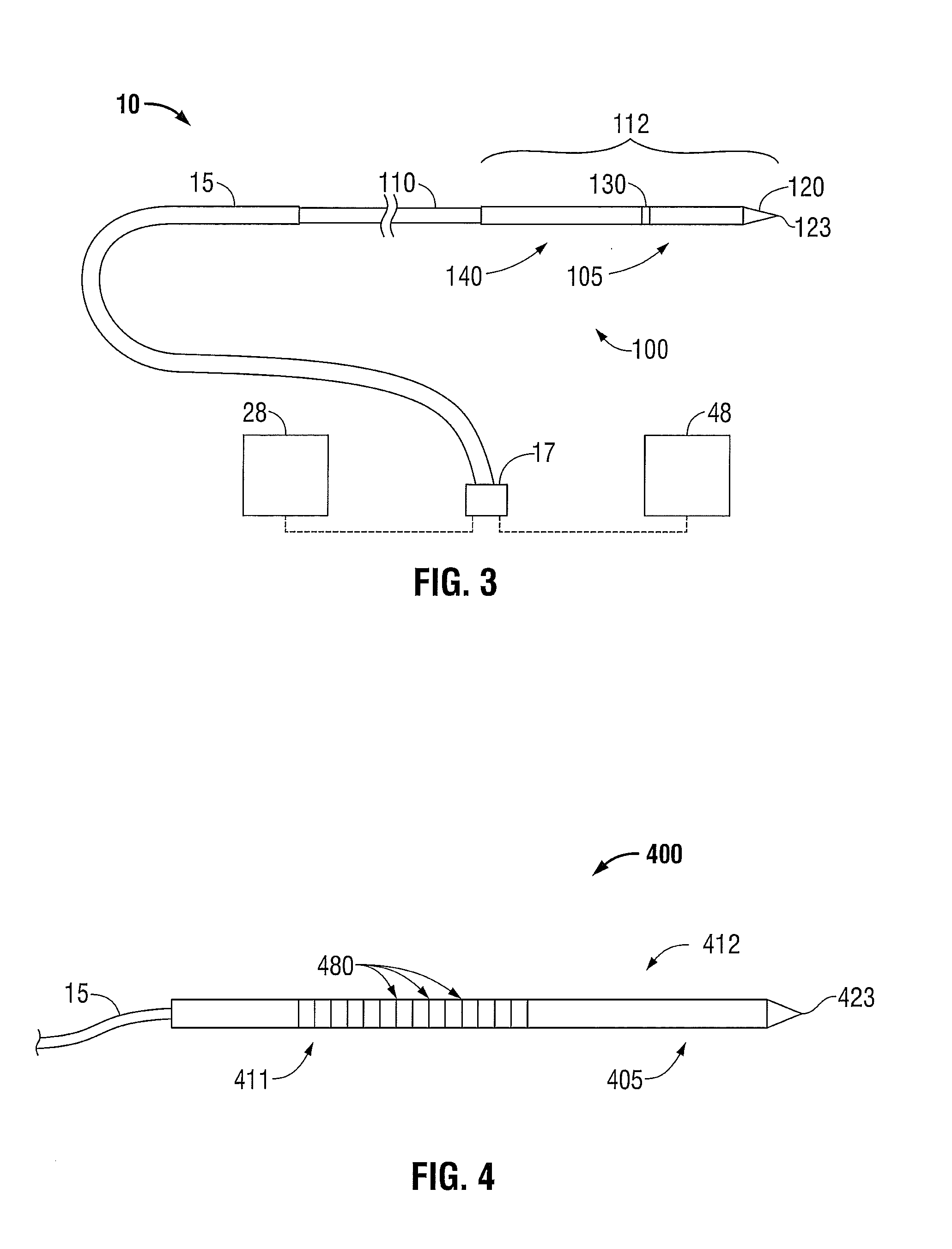
[0030]Hereinafter, embodiments of the presently-disclosed data acquisition module operably associated with an energy applicator, electrosurgical power generating source operably associated therewith, and electrosurgical systems including the same, and the presently-disclosed methods of directing energy to tissue, are described with reference to the accompanying drawings. Like reference numerals may refer to similar or identical elements throughout the description of the figures. As shown in the drawings and as used in this description, and as is traditional when referring to relative positioning on an object, the term “proximal” refers to that portion of the device, or component thereof, closer to the user and the term “distal” refers to that portion of the device, or component thereof, farther from the user.

[0031]This description may use the phrases “in an embodiment,”“in embodiments,”“in some embodiments,” or “in other embodiments,” which may each refer to one or more of the same or


PUM


Abstract

An electrosurgical system includes an electrosurgical power generating source, an energy applicator operably associated with the electrosurgical power generating source, a processor unit, and a data acquisition module configured to receive a reflected signal. The processor unit is disposed in operative communication with the data acquisition module and adapted to determine a tissue desiccation rate around at least a portion of the energy applicator based on one or more signals received from the data acquisition module.

Description


Claims


Application Information

Patent Timeline
Owner TYCO HEALTHCARE GRP LP
Why Eureka
Try Eureka