Battery monitoring system

a battery monitoring and battery technology, applied in the field of battery monitoring systems, can solve the problems of complex battery pack design of electric vehicles (evs), and achieve the effects of simple manufacturing, easy installation, and low cos

Inactive Publication Date: 2014-01-02
AEES INC
View PDF8 Cites 6 Cited by
  • Summary
  • Abstract
  • Description
  • Claims
  • Application Information

AI Technical Summary

Benefits of technology

The technical effect of this new design is its ability to connect batteries with electronic devices like computers without requiring expensive wires or other connections between them. This makes it easier than previous designs because there are no extra components needed at all.

Problems solved by technology

This patented describes how batteries used on Evolving Buses (Electric Vans), such as those powered by an engine like gasoline-powered cars, work better than traditional car models due to its high efficiency compared to other forms of transportation. Additionally, it suggests adding more advanced components within each cell to manage them properly during charging cycles.

Method used


Image

  • Battery monitoring system
  • Battery monitoring system
  • Battery monitoring system

Examples


Embodiment Construction

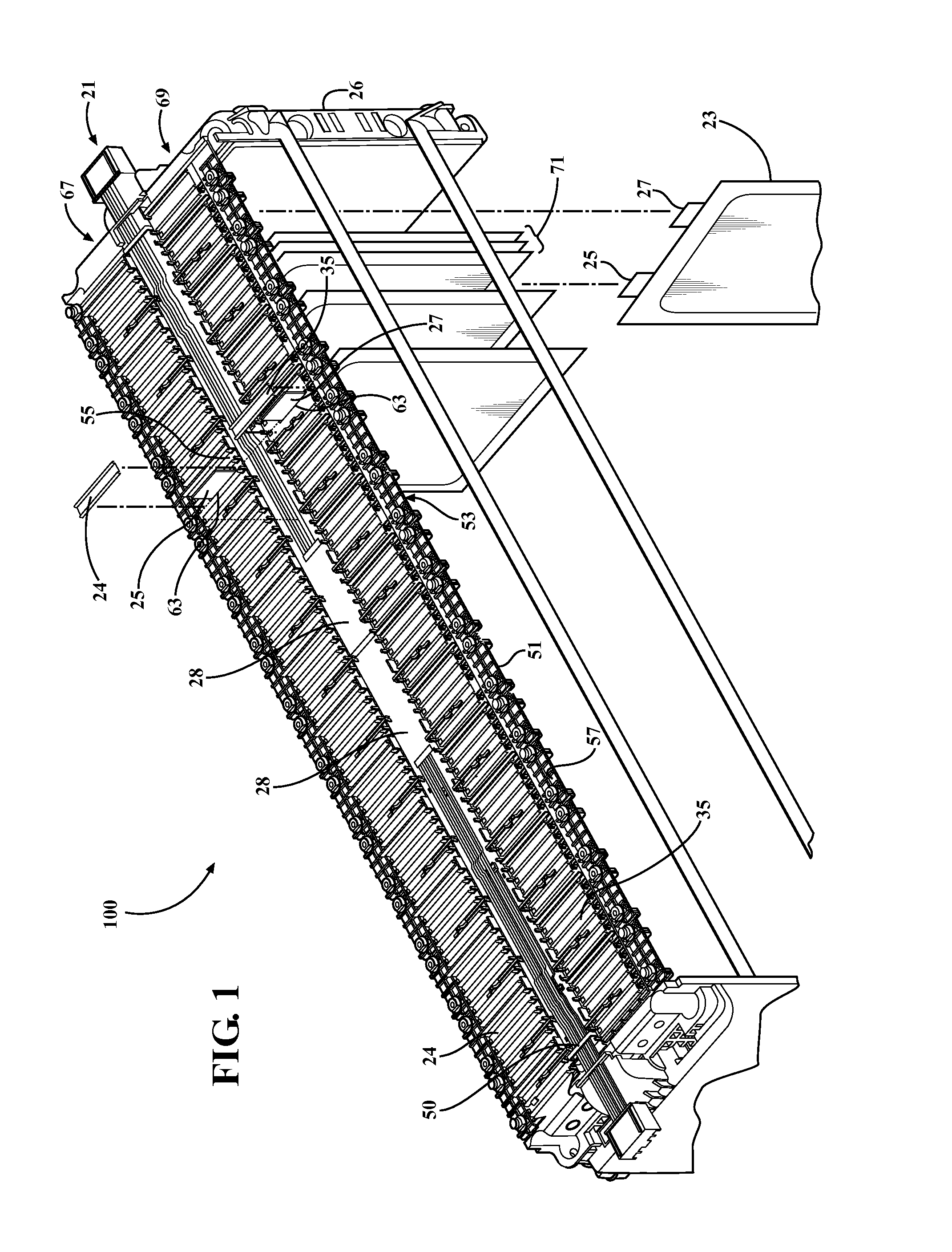
[0035]Referring to the Figures, wherein like numerals indicate corresponding parts throughout the several views, a battery monitoring system 100 which may be implemented in a battery assembly 22 for battery electric vehicle (BEV) applications is provided.

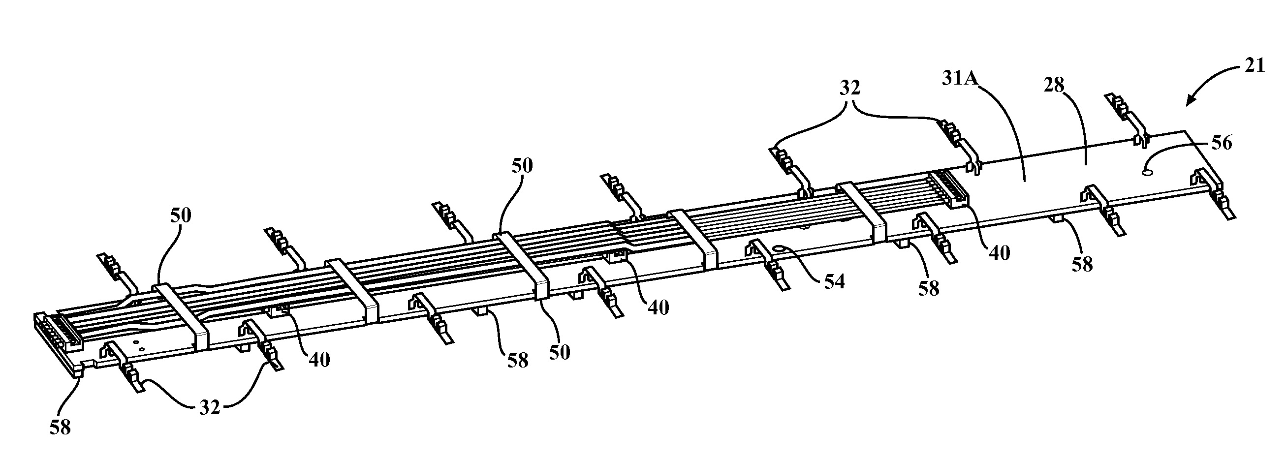
[0036]Referring now to FIGS. 1-3, the battery assembly 22 includes one or more battery cells 23, typically lithium ion batteries. As best shown in FIG. 3, the battery cells 23 each include a positive battery terminal 25 and a negative battery terminal 27. The battery cells 23 can have different chemistry, physical shapes, and sizes than the one depicted in representative FIG. 3 and can be organized into one or more battery modules 71.

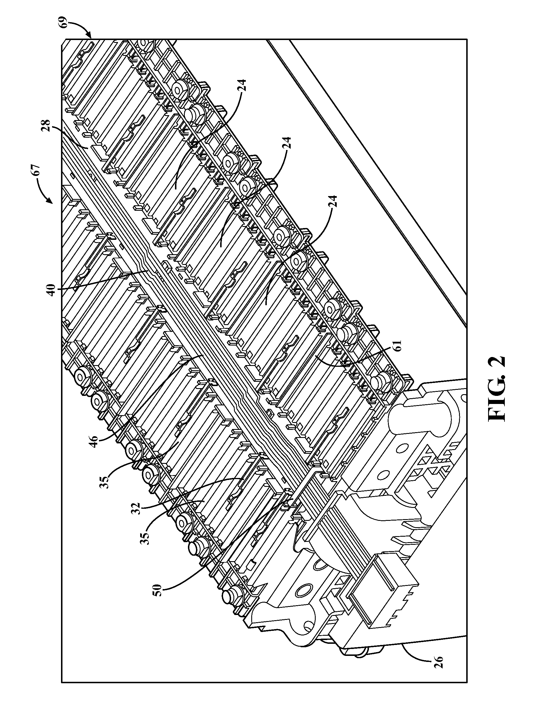
[0037]The battery assembly 22 also includes a non-conductive housing 51 having an inner portion 53 and an outer portion 57. The outer portion 57 includes a plurality of slots 55 preferably organized into a pair of rows 67, 69, wherein the plurality of adjacent slots 55 in a single row 67 or 69 are separate


PUM


Abstract

A battery monitoring system for monitoring a state of a battery assembly that includes a connection assembly for electrically coupling a controller to the battery assembly. The connection assembly includes a circuit board having an edge extending from a top surface to a bottom surface. The connection assembly also includes a plurality of terminals each having a first end electrically coupled to the circuit board and a second end electrically coupled to the battery assembly with the second end extending beyond the edge of the circuit board with the plurality of terminals each being resiliently biased against the battery assembly for accommodating relative movement between the battery assembly and said circuit board.

Description


Claims


Application Information

Patent Timeline
Owner AEES INC
Why Eureka
Try Eureka