Modular interface for pantry temperature control

Inactive Publication Date: 2014-05-29
WHIRLPOOL CORP
View PDF1 Cites 23 Cited by
  • Summary
  • Abstract
  • Description
  • Claims
  • Application Information

AI Technical Summary

Benefits of technology

[0005]It is a further object, feature, or advantage of the present invention to provide a refrigerator with a pantry drawer with separate temperature control.
[0006]It is a still further object, feature, or advantage of the present invention to provide a pantry drawer which may be configured for either electronic or manual temperature control.
[0007]Another object, feature, or advantage of the present invention is to provide for standardization of parts across different platforms for refrigerators.
[0008]Yet another object, feature, or advantage of the present invention is to provide for manufacturing refrigerators with drawers with different types of temperature controls in a manner that is cost effective and efficient.
[0009]One or more of these and/or other objects, features, or advantages of the present invention will become apparent from the Specification and claims that follow. No single embodiment need meet all of these objects, features, or advantages and different embodiments may meet different objects, features, or advantages. The present invention is not to be limited by or to these objects, features, or advantages.
[0010]According to one aspect of the present invention, a refrigerator is provided. The refrigerator includes a refrigerator cabinet, a refrigerator compartment disposed within the refrigerator compartment, a drawer within the refrigerator compartment, a cover on a top of the drawer, a plurality of apertures in the cover, and controls on the cover for controlling temperature within the drawer. The cover is configured to be positioned between a user interface assembly and a user interface cover with screws through the apertures in a first configuration wherein the controls are electronic controls for controlling temperature within the drawer. The cover is further configured to be snapped to a control housing using the plurality of apertures for alignment in a second configuration wherein the controls are manual controls for controlling the temperature within the drawer.

Problems solved by technology

Yet there are problems in manufacturing such refrigerators.
One of the problems associated with manufacturing such refrigerators relates to the desire to provide for standardization of parts across different platforms.

Method used


Image

  • Modular interface for pantry temperature control
  • Modular interface for pantry temperature control
  • Modular interface for pantry temperature control

Examples


Example

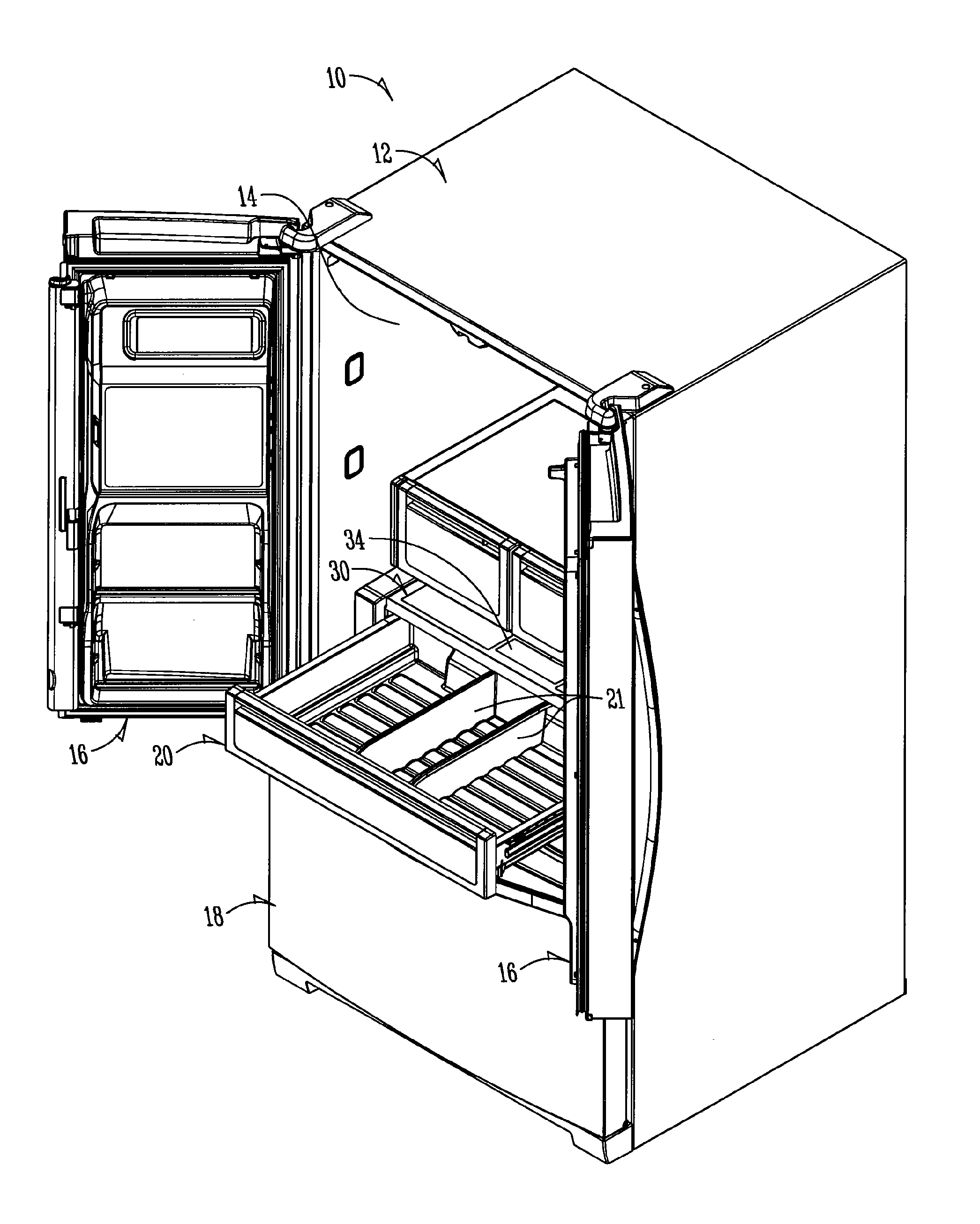
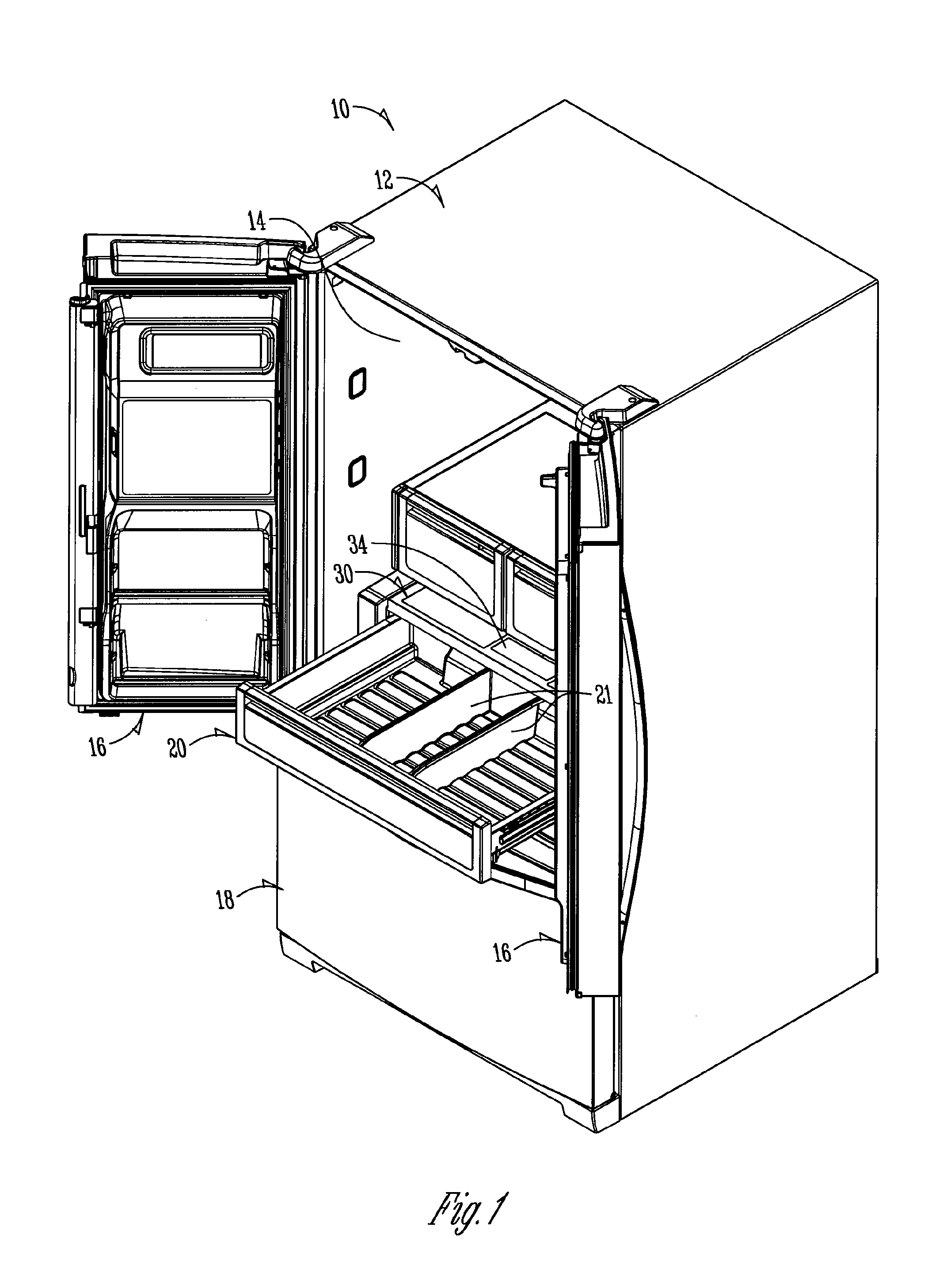
[0023]FIG. 1 illustrates a refrigerator 10. The refrigerator 10 has a refrigerator cabinet 12. There is a fresh food or refrigerator compartment 14 positioned above a freezer compartment with a freezer drawer 18 providing access to the freezer compartment and the French doors 16 providing access to the refrigerator compartment 14. A pantry drawer 20 is shown. The pantry drawer 20 preferably extends the full width and depth of the refrigerator compartment 14 and may have one or more dividers 21 therein for organizing contents within the pantry drawer 20. The pantry drawer 20 may have a temperature which is different from the refrigerator compartment 14 depending upon user preferences which may be based in part on the items which a user decides to store in the pantry drawer 20.

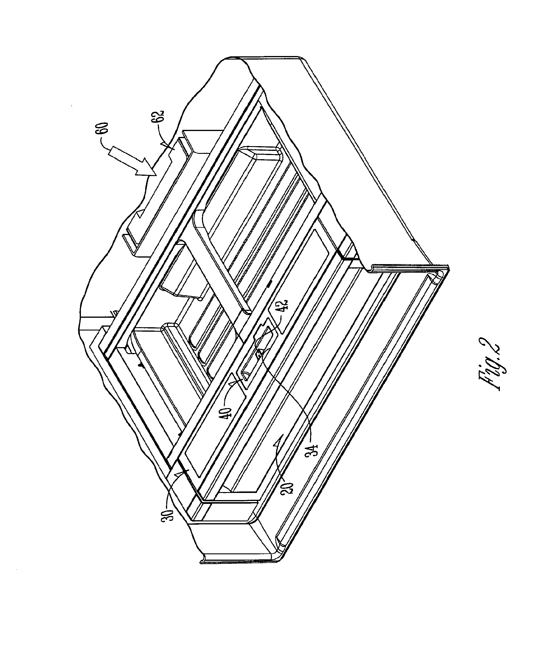
[0024]The pantry drawer 20 has a top cover 30 which extends generally along its length. In a central portion of the top cover 30, a receiver 34 is present in which user interface controls may be positioned to provi


PUM

PropertyMeasurementUnit
Temperatureaaaaaaaaaa
Lengthaaaaaaaaaa

Abstract

A refrigerator includes a refrigerator cabinet, a refrigerator compartment disposed within the refrigerator compartment, a drawer within the refrigerator compartment, a cover on a top of the drawer, a plurality of apertures in the cover, and controls on the cover for controlling temperature within the drawer. The cover is configured to be positioned between a user interface assembly and a user interface cover with screws through the apertures in a first configuration wherein the controls are electronic controls for controlling temperature within the drawer. The cover is further configured to be snapped to a control housing using the plurality of apertures for alignment in a second configuration wherein the controls are manual controls for controlling the temperature within the drawer.

Description


Claims


Application Information

Patent Timeline
Owner WHIRLPOOL CORP
Why Eureka
Try Eureka