Limit switch
a technology of limit switch and switch body, which is applied in the direction of contact mechanism, electrical apparatus, and protective device for calibrating/seeing, etc., can solve the problems of low detection sensitivity and small displacement amount, and achieve good production yield
- Summary
- Abstract
- Description
- Claims
- Application Information
AI Technical Summary
Benefits of technology
Problems solved by technology
Method used
Image

Examples
first embodiment
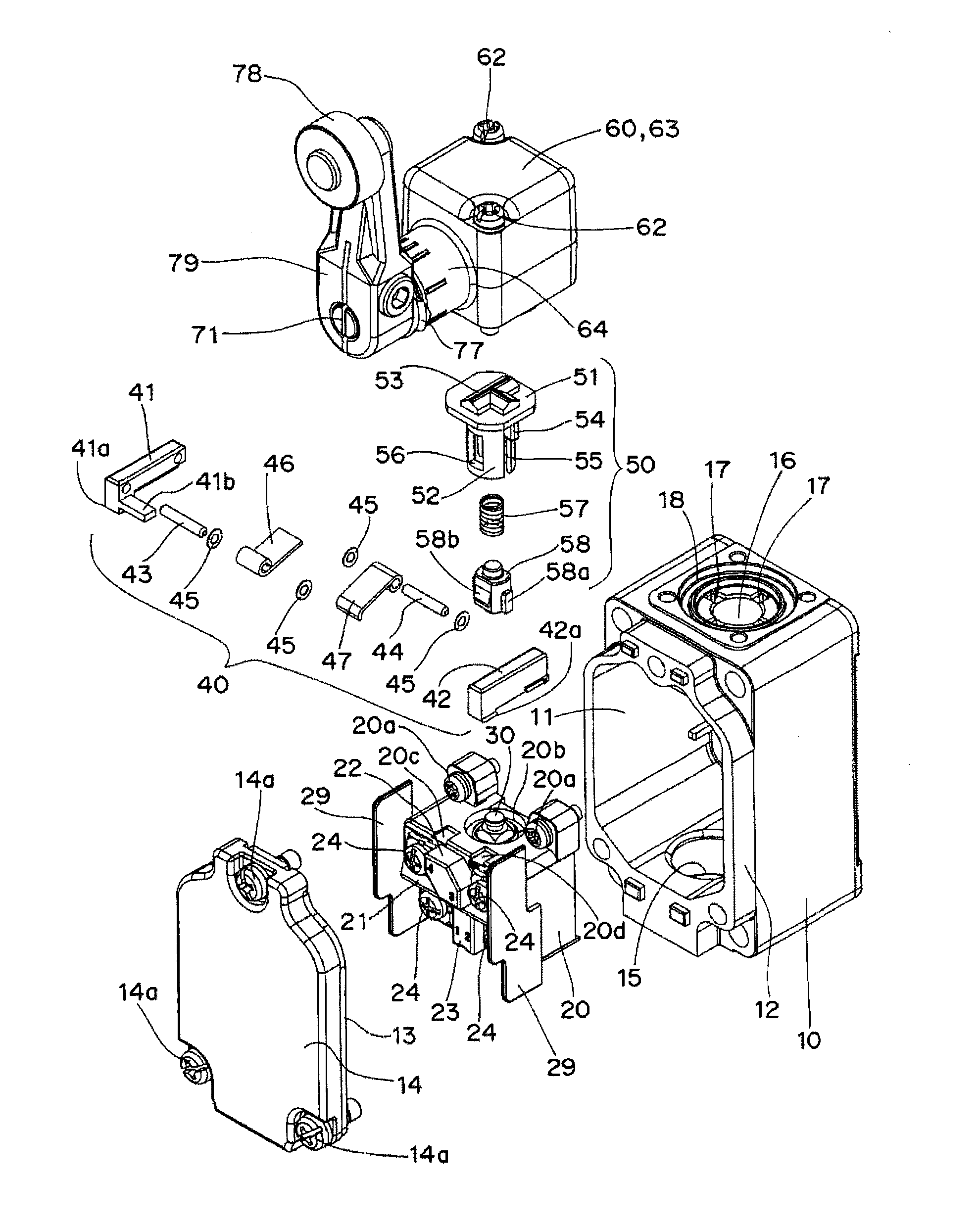
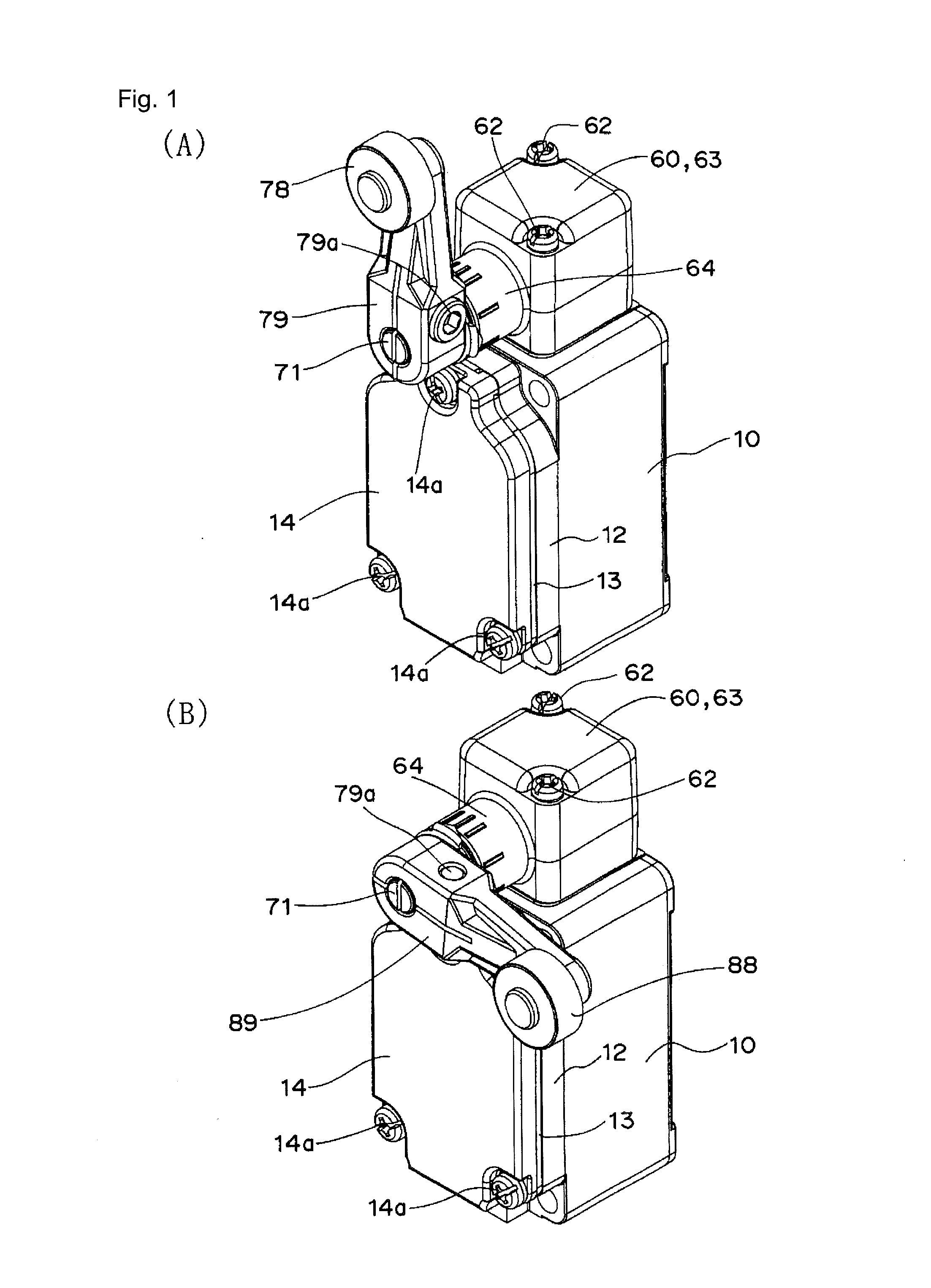
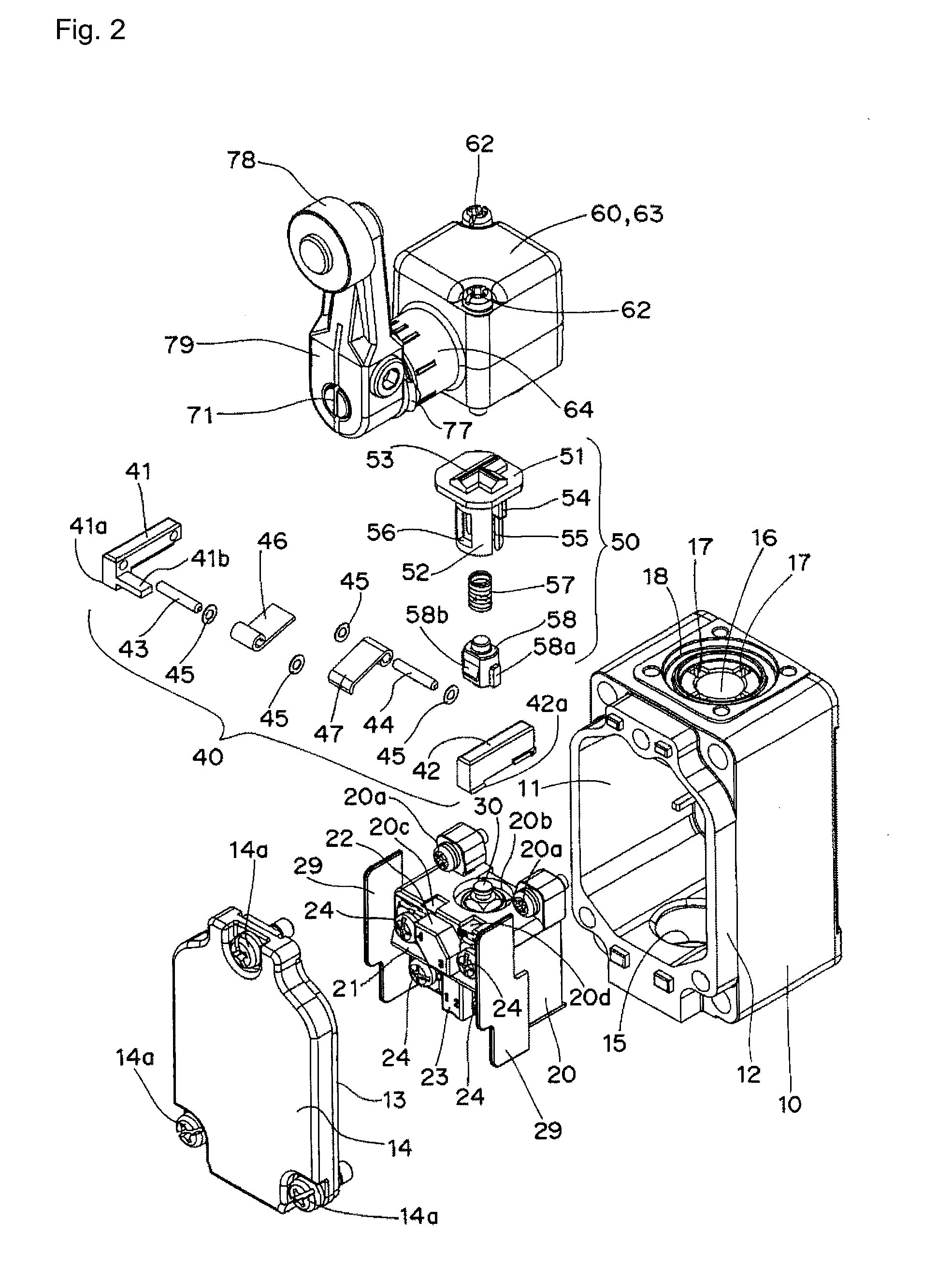
[0029]As illustrated in FIGS. 1 to 8, a limit switch includes displacement expanding mechanism 40, and switch main body 20 assembled in housing 10 is driven by driving mechanism 60 including operation lever 79 through plunger 50.
[0030]As illustrated in FIGS. 2 and 3, housing 10 has a box shape in which switch main body 20 can be accommodated, and circular rib 12 is formed along opening 11 provided in a front surface of housing 10. Circular seal member 13 is positioned in circular rib 12, and cover 14 is fixed to housing 10 by fixing screws 14a, thereby sealing opening 11. Connection hole 15 is made in a bottom surface of housing 10, and operation hole 16 is made in a ceiling surface of housing 10. Positioning slits 17 are radially formed in an inner circumferential surface of operation hole 16 at intervals of 90 degrees, and circular step 18 is concentrically formed near an opening edge of operation hole 16.
[0031]Switch main body 20 has an outer shape of which switch main body 20 can
fourth embodiment
[0061]As is clear from the fourth embodiment, because the ratio of the leverage can be changed without changing the shapes of pivoting tongue pieces 46 and 47, a degree of design freedom is advantageously increased.
[0062]Although not illustrated, the fixing position of displacement expanding mechanism 40 may be varied when engagement claws 41a and 42a provided in support plates 41 and 42 of displacement expanding mechanism 40 are fixed to engagement grooves 20c and 20d provided in the ceiling surface of housing 10 by the slide-fitting. When the fixing position of the displacement expanding mechanism 40 is varied, advantageously the ratio of the leverage can finely be adjusted even after the assembly to improve a production yield.
[0063]For the same reason, a position adjusting elongated hole may be used as a screw hole through which switch main body 20 is fixed by fixing screw 20a.
[0064]The operation lever is not necessarily attached in the vertical direction. For example, the operatio
PUM
 Abstract
Description
Claims
Application Information
 - R&D Engineer
- R&D Manager
- IP Professional
- Industry Leading Data Capabilities
- Powerful AI technology
- Patent DNA Extraction
Browse by: Latest US Patents, China's latest patents, Technical Efficacy Thesaurus, Application Domain, Technology Topic.
© 2024 PatSnap. All rights reserved.Legal|Privacy policy|Modern Slavery Act Transparency Statement|Sitemap