Apparatus for the orientation and positioning of surgical instruments and of implantation prosthesis in a bone seat

Inactive Publication Date: 2016-02-11
DIAL MEDICALI
View PDF5 Cites 37 Cited by
  • Summary
  • Abstract
  • Description
  • Claims
  • Application Information

AI Technical Summary

Benefits of technology

[0031]FIG. 14 shows the rear side of the central con

Problems solved by technology

However, that means that application defects may arise—as they have in fact really arisen, even though sporadically and due to inadequate operating conditions—which have caused a painful condition to the patient, walking difficulties or even the need to repeat the surgical operation to change the implant positioning.
Scientific research has highlighted that the main source of mechanical complications is especially an incorrect positioning of the prostheses.
This problem has become more evident in more recent years, in which techniques and implantation methods have been studied which resort to numerically-controlled biotechnology.
Such an apparatus, despite allowing to provide the surgeon with objective and real information of the exact orientation of the surgical instrument with respect to the patient's bone, still suffers from some remarkable drawbacks, and in particular:the need to locate three reference positions on the patient's bone, and to fasten on the patient's body the device which allows to determine the position of the first sensor significantly complicates the use of the system and causes a remarkable lengthening of the operation times, with respect to traditional surgery, with a consequent greater patient burden;the mechanical device for determining the position of the first sensor must furthe

Method used


Image

  • Apparatus for the orientation and positioning of surgical instruments and of implantation prosthesis in a bone seat
  • Apparatus for the orientation and positioning of surgical instruments and of implantation prosthesis in a bone seat
  • Apparatus for the orientation and positioning of surgical instruments and of implantation prosthesis in a bone seat

Examples


first embodiment

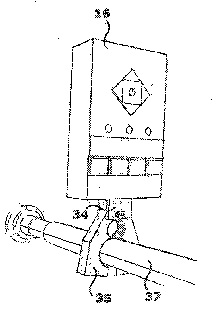
[0049]In the invention, illustrated in FIG. 10A, box 26 embeds position detection means and signalling means of the detected position. On the front of the box an activation button 28 and a signalling light 29 are available.

[0050]The position detection means and the detected position signalling means within box 26 belong to the prior art, according to which different possible technical ways are provided for providing an accurate position detection, i.e. a detection which univocally determines the position and the orientation in space of the fixed sensor 17 with the desired precision degree, for example using gyroscopes, accelerometers or magnetometers. Such technical ways are not disclosed here in detail since they do not fall within the scope of protection of the present invention.

second embodiment

[0051]In the invention, illustrated in FIG. 10B, box 26 contains no intelligent function, but represents a simple support 26a of 4 or more blocks of reflective material 29a, 29b, 29c, 29d, so as to allow the remote detection of the exact position of said support 26a, and hence of the pelvis during surgery, through the analysis of a light radiation reflected by said blocks 29, as better described in the following.

[0052]The compasses-like instrument 15 is in turn in the shape of a support 30 to which two legs 32 are connected below, which legs may be spread apart and adjusted in position in the way better described in the following. Above, support 30 is provided with a tang 31, meant to be inserted precisely (and in a single position) into the hole 16a formed in the lower face of central unit 16, in the way highlighted in FIG. 13.

[0053]Clamp 18 consists of a base 33, from which a tang 34 projects upwards 34 (fully identical to tang 31) for the coupling with central unit 16. To the lower


PUM


Abstract

Apparatus for the fast angular orientation of a surgical instrument with respect to an implantation seat of a prosthesis in a patient's bone, of the type comprising a moving sensor, which may be associated with the surgical instrument, and a fixes sensor, which may be integrally fastened to the bone during a surgical operation, the moving sensor and the fixed sensor being provided with a position detection device and with a device for signaling of the detected position to a central memory and processing unit. The central memory and processing unit comprises calibration device which detect the position of the moving sensor when it is associated with a line passing through two known points of the bone and, simultaneously, they detect the position of the fixed sensor when it is integrally fastened to the bone, and they record such position as initial work position.

Description


Claims


Application Information

Patent Timeline
Owner DIAL MEDICALI
Why Eureka
Try Eureka