Master cylinder

a master cylinder and cylinder body technology, applied in the direction of rotary clutches, braking systems, fluid couplings, etc., can solve the problems of inability to immediately open the relief port and release the residual pressure, and achieve the effect of further ensuring the response during brake actuation and improving the release delay during brake releas

Active Publication Date: 2016-07-14
BOSCH CORP
View PDF1 Cites 0 Cited by
  • Summary
  • Abstract
  • Description
  • Claims
  • Application Information

AI Technical Summary

Benefits of technology

The technical effect of this patented design is that it improves upon how well the response time for brakes starts when they are being used on vehicles. It also enhances the ability to automatically stop or slow down while still maintaining enough force to prevent damage from overheated tires.

Problems solved by technology

The technical problem addressed in this patent is how to prevent excessive supply of hydraulic fluid to the brakes while also allowing for quick response time without slow down the movement of the wheel due to negative pressure conditions.

Method used


Image

  • Master cylinder
  • Master cylinder
  • Master cylinder

Examples


Embodiment Construction

[0022]An embodiment of the application of the present invention will be described below with reference to the drawings.

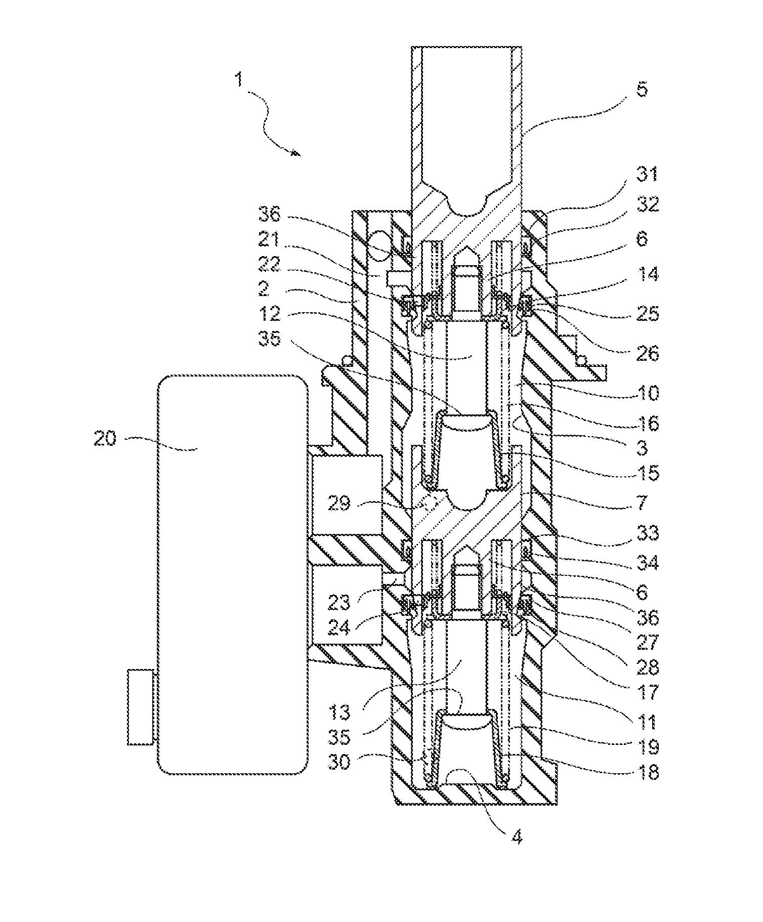
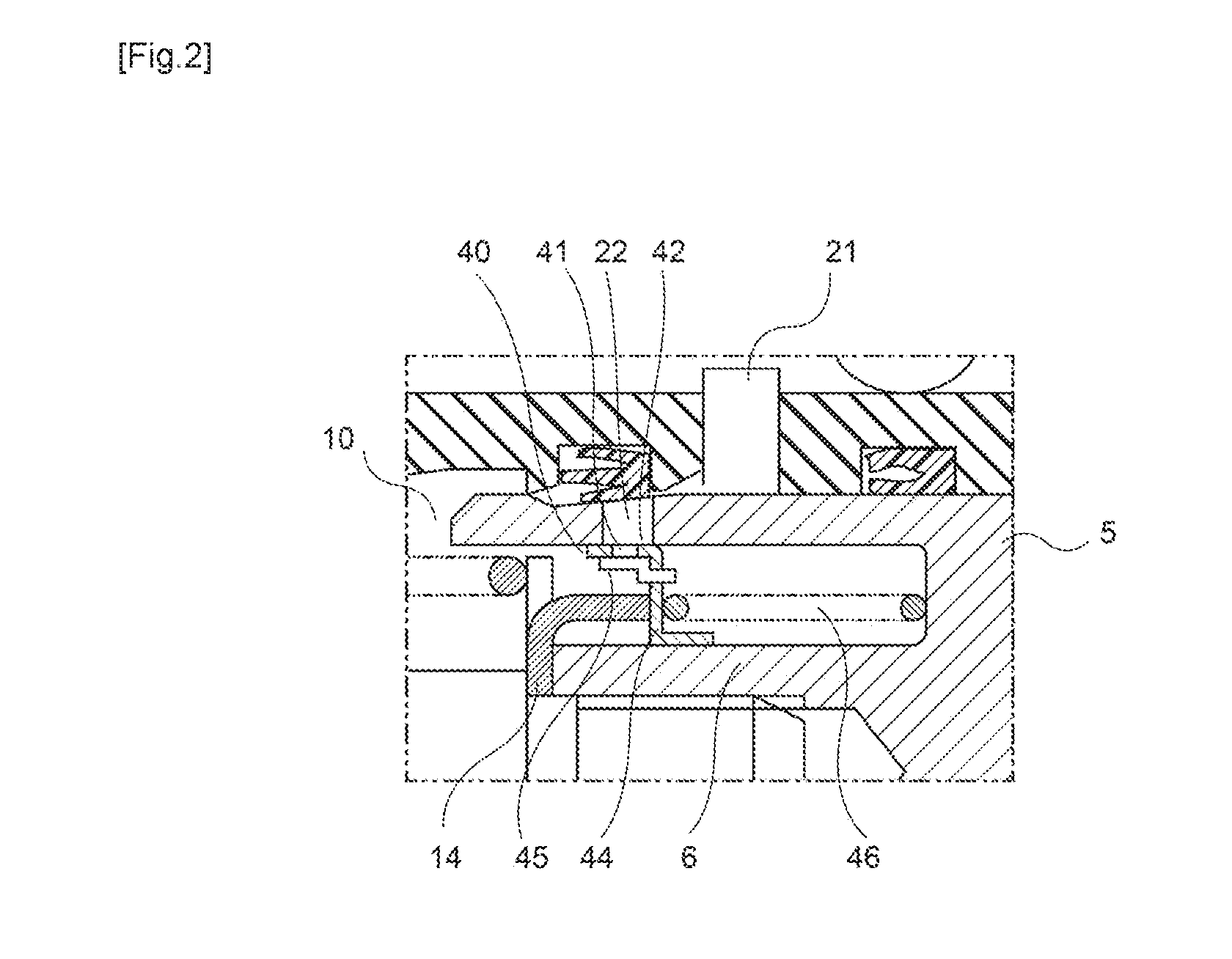
[0023]FIG. 1 illustrates an entire master cylinder according to an embodiment of the present invention. As illustrated in FIG. 1, a plunger type master cylinder 1 has a cylinder body 2 and a cylinder hole 3 is formed in the cylinder body 2.

[0024]A primary piston 5, which is an example of pistons according to the invention, and a secondary piston 7, which is also an example of pistons according to the invention, are slidably inserted into the cylinder hole 3. The primary piston 5 is moved to the left by a brake pedal (not illustrated) or a brake booster boosting and outputting the depressing force of the brake pedal. The primary piston 5 and the secondary piston 7 partition and form a first hydraulic chamber 10 between the primary piston 5 and the secondary piston 7 and partition and form a second hydraulic chamber 11 between the secondary piston 7 and a bottom 4 of the


PUM


Abstract

An object is to provide a master cylinder that ensures the responsivity during brake actuation, improves a release delay during brake release, ensures the responsivity during automatic braking, and quickly releases the residual pressure in the hydraulic chamber.
The master cylinder includes a cylinder body having a cylinder hole, a piston slidably inserted into the cylinder hole, the piston partitioning a hydraulic chamber, a communicating passage provided in the cylinder body, the communicating passage communicating with a reserver, a relief port formed in the piston, the relief port performing communication between the communicating passage and the hydraulic chamber, and a seal member housed in a recess portion in an inner peripheral surface of the cylinder hole of the cylinder body, the piston slidably passing through the seal member, the seal member performing sealing between the inner peripheral surface of the cylinder hole and an outer peripheral surface of the piston, the communicating passage communicating with the relief port during non-actuation, the piston moving to block the communicating passage from the relief port using the seal member during actuation, in which a flow passage control member for opening and closing the relief port is provided in a part of the relief port close to the hydraulic chamber.

Description


Claims


Application Information

Patent Timeline
Owner BOSCH CORP
Why Eureka
Try Eureka