Temporary structure

a temporary structure and structure technology, applied in the field of temporary structures, can solve the problems of insufficient strength and stability inability to withstand wind, complex structure, and insufficient strength of the current art tent, and achieve the effect of superior strength and support, easy transportation, and us

Inactive Publication Date: 2016-11-24
RIZZOTTO SCOTT
View PDF13 Cites 10 Cited by
  • Summary
  • Abstract
  • Description
  • Claims
  • Application Information

AI Technical Summary

Benefits of technology

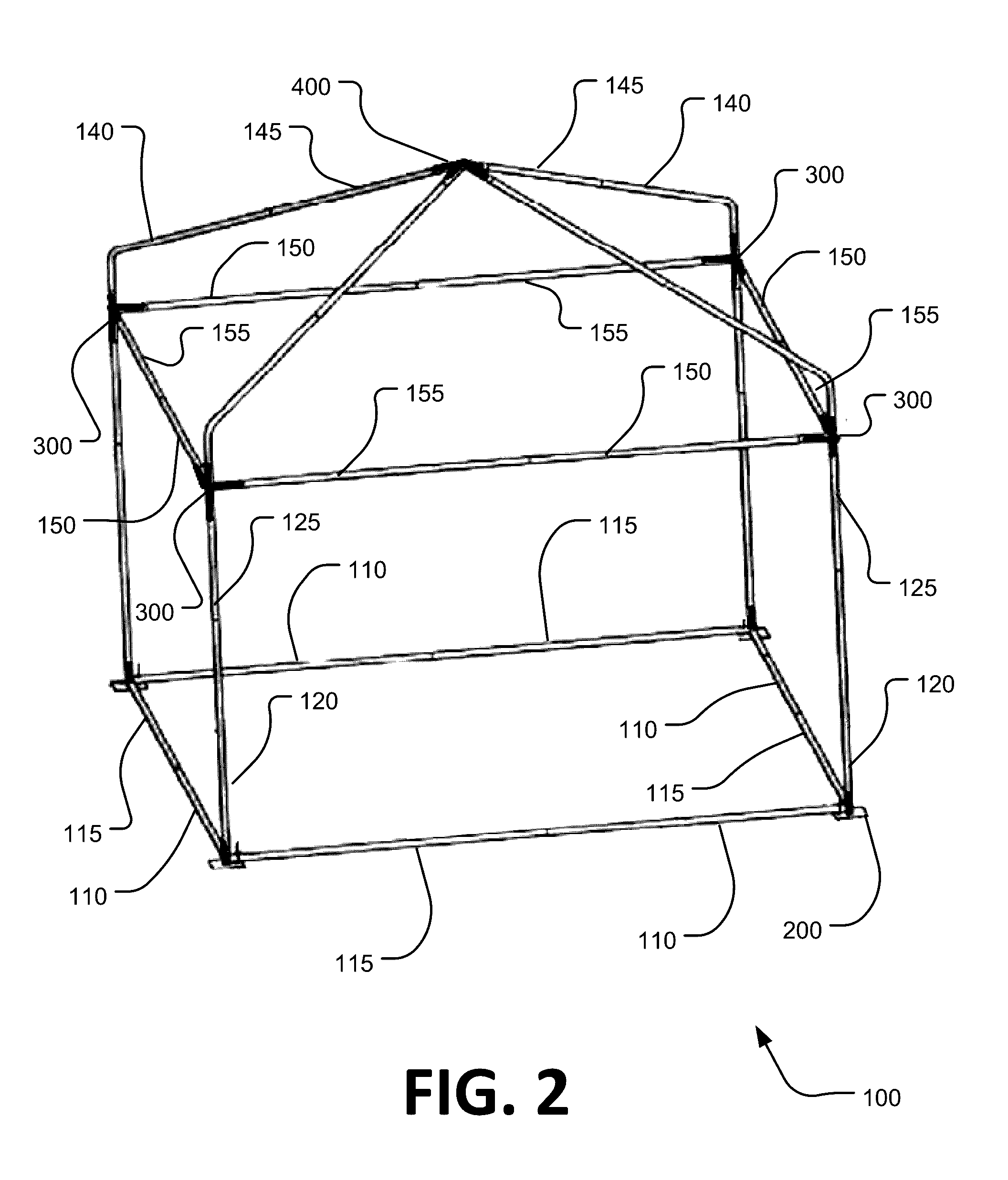
This new type of temporary shelter has several technical features: it uses strong frames made from weldable material like steel or aluminum for easy carriage, assembly, use, storage, reassembly, etc., making them very durably against various environmental factors such as water damage caused by precipitation (rain) during winter months). Additionally, they are designed with flexible outer covers that fit well on these frames without losing their shape when exposed to severe environments over time. Overall, this innovation improves the functionality and usability of temporary structures for multiple purposes.

Problems solved by technology

The technical problem addressed by this patented technology relates to improving temporary structures used during periods where individuals live or travel without having them at risk from weather conditions such as rain or snow. These existing tentings may lack sufficient stability but still require extra weight and complexity compared to traditional methods like ladders or scaffolding.

Method used


Image

  • Temporary structure
  • Temporary structure
  • Temporary structure

Examples


Embodiment Construction

[0025]In the following discussion, numerous specific details are set forth to provide a thorough understanding of the present disclosure. However, those skilled in the art will appreciate that embodiments may be practiced without such specific details. Furthermore, lists and / or examples are often provided and should be interpreted as exemplary only and in no way limiting embodiments to only those examples. Similarly, in this disclosure, language such as “could, should, may, might, must, have to, can, would, need to, is, is not”, etc. and all such similar language shall be considered interchangeable whenever possible such that the scope of the invention is not unduly limited. For example, a comment such as: “item X is used” can be interpreted to read “item X can be used”.

[0026]Exemplary embodiments are described below and in the accompanying Figures. The following detailed description provides a review of the drawing Figures in order to provide a thorough understanding of, and an enab


PUM


Abstract

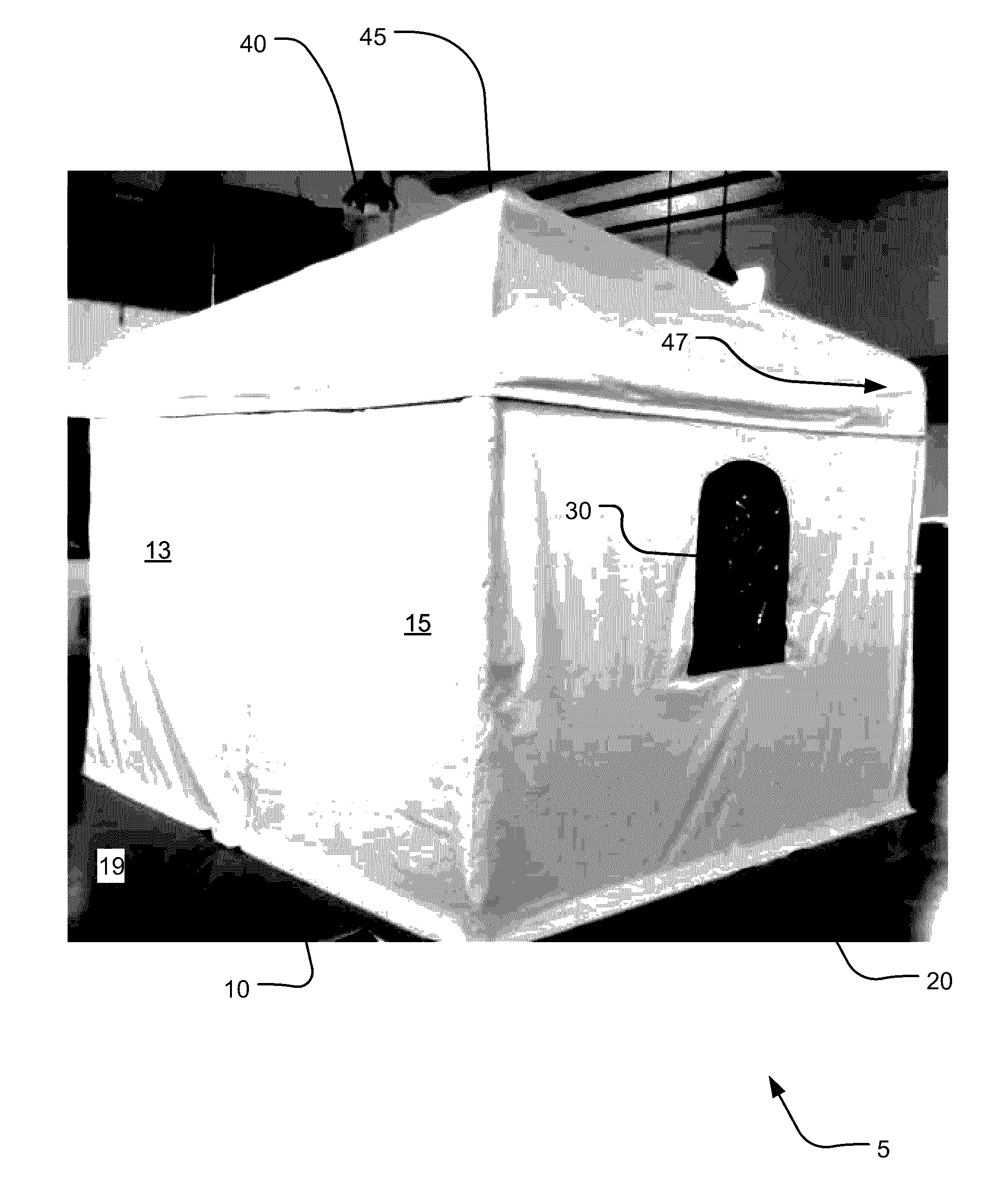
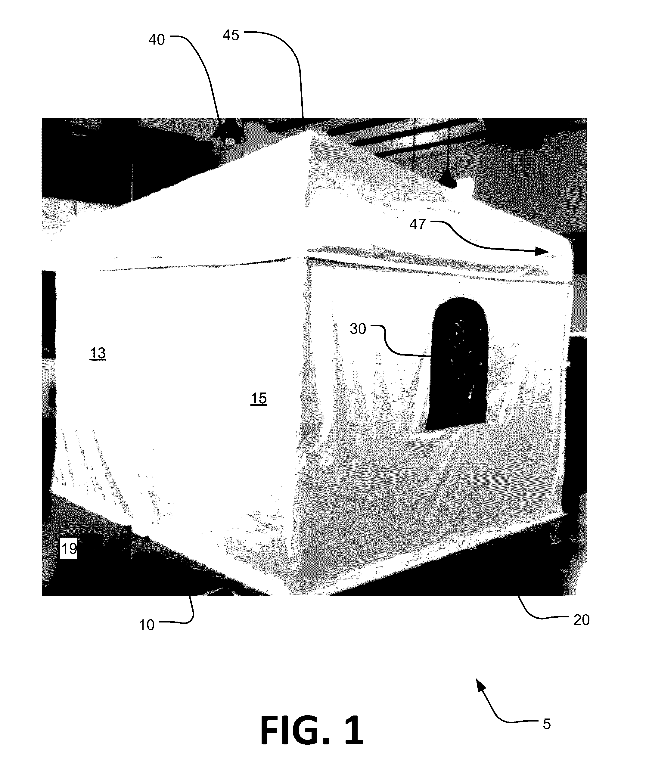
An improved temporary structure utilizes an enhanced, heavy-duty frame that is specially engineered to be easily transported, assembled, used and then disassembled and transported again, all while simultaneously providing superior strength and support to the shell covering and flexibility in configuration to meet the varying needs of a myriad of different users. The exterior shell covering can be constructed of tough, all-weather materials that can handle rain, wind, sleet, snow, sun, sand, and other harsh conditions while staying attached to the frame and properly supported thereby; the two working in concert to provide a much improved temporary structure.

Description


Claims


Application Information

Patent Timeline
Owner RIZZOTTO SCOTT
Why Eureka
Try Eureka