Location independent lighting sensor system
- Summary
- Abstract
- Description
- Claims
- Application Information
AI Technical Summary
Problems solved by technology
Method used
Image

Examples
embodiment 500
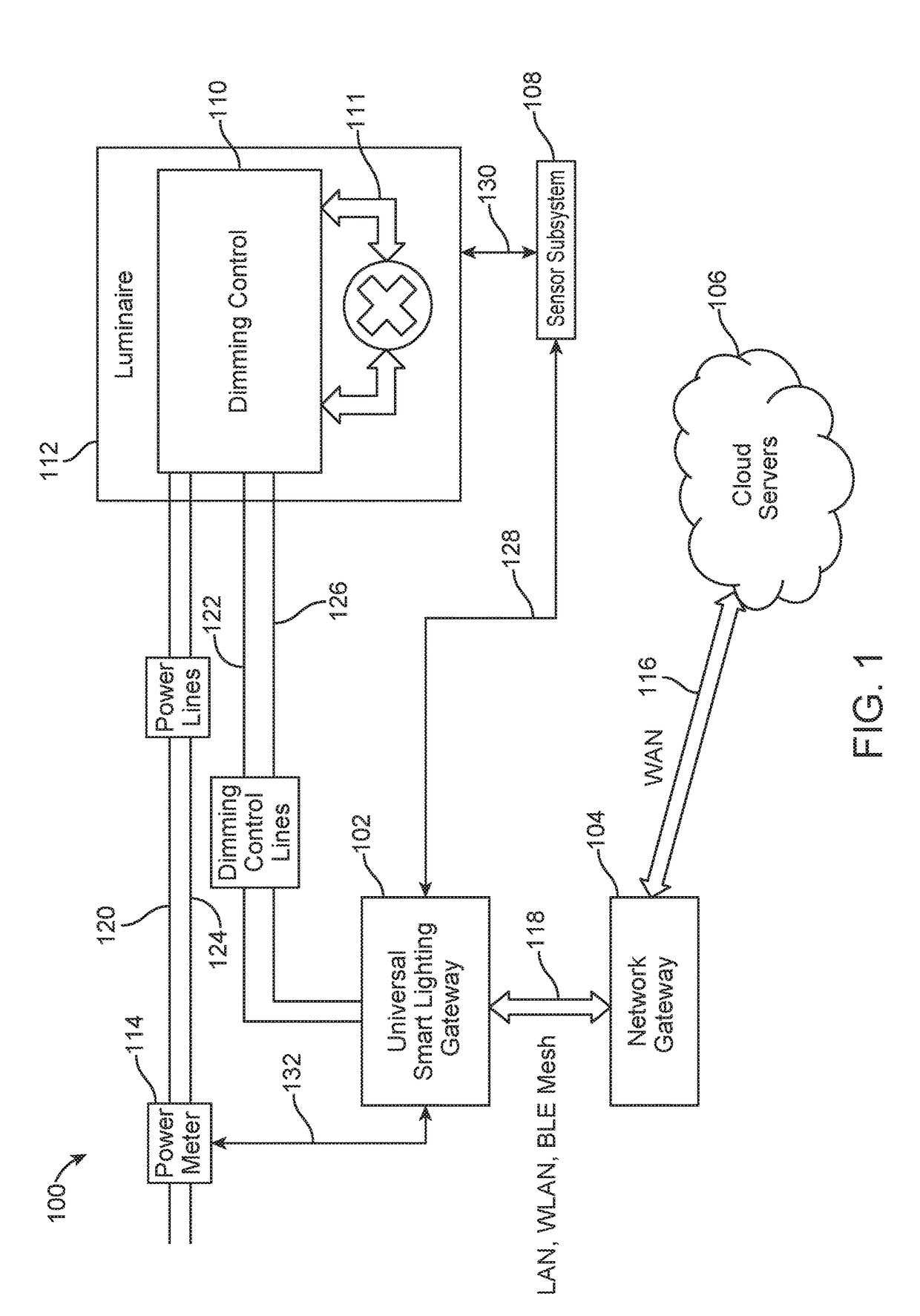
[0097]FIG. 5 depicts an embodiment 500 of the system 100 handling of device setup and discovery operations starting at step 410. Step 410 includes the discovery and proper set-up of the device / the luminaire. The setup and discovery operations may include a flow of information that occurs as two separate parts of the system 500, each including a request for information (RFI) 516 flow to server 106 and a flow from the server 106 of Information 518, which may include minimal initialization information from a particular controlled luminaire (as described above with reference to, for example, FIG. 1).
[0098]According to an aspect, the first event after turning on a gateway 102 may include the RFI 516 being sent / transmitted from the gateway 102 to the server 106. As illustrated in FIG. 5, at step 502, the gateway 102 may send the RFI 516 towards the server 106. It is also possible to get to step 501 via step 550 which is a re calibration trigger by the server 106. The gateway 102 may ask
embodiment 600
[0100]FIG. 6 illustrates an embodiment 600 of the gateway standard operation mode 530. At step 602 gateway 102 is primarily in a sleep mode during which it waits for one or more events to occur. In an embodiment, each event may include setting a new dimming level and waiting for a single sensor event or multiple sensor events. According to an aspect, the types of the events the gateway may wait to occur include two types. The first type of event may be associated with existing dimming and testing, including, for example, at a specific / designated time, setting a specific dimming level, and waiting for a set of sensor readings. For instance, at step 622, a “receive scheduling and parameters updates” process 622 may update the dimming and test schedule DB 524 and may also refresh a sleeping timer (not shown) for the gateway to wake at the next appropriate test schedule. According to an aspect, the second type of event includes current / present sensor readings that need to be read and p
embodiment 700
[0106]FIG. 7 illustrates an embodiment 700 of the creating ‘Updates Message’620 described hereinabove and illustrated in FIG. 6. According to one aspect, the creating of the Updates Message may depend on the accumulation of all prior messages sent and recorded in the Message Status DB 618. Based on past / previous messages and current event information stored in the events DB 612, the gateway may identify sensor readings that have changed and may format a message to include those readings only, and send this message to cloud server 106. According to an aspect shown in FIG. 6, once this message is sent, the message status DB 618 may be updated for future analysis, and the gateway may go back to sleep and wait for the occurrence of any next events as part of the standard operational mode 530.
[0107]As illustrated in FIG. 7, step 702 receives messages from the message status DB 618, and gateway 102 may identify the last baseline message sent and the updates message that followed. At step 7
PUM
 Abstract
Description
Claims
Application Information
 - R&D Engineer
- R&D Manager
- IP Professional
- Industry Leading Data Capabilities
- Powerful AI technology
- Patent DNA Extraction
Browse by: Latest US Patents, China's latest patents, Technical Efficacy Thesaurus, Application Domain, Technology Topic.
© 2024 PatSnap. All rights reserved.Legal|Privacy policy|Modern Slavery Act Transparency Statement|Sitemap