Fine particle manufacturing device

a technology for manufacturing devices and fine particles, which is applied in the direction of material granulation, transportation and packaging, chemical/physical/physicochemical processes, etc., can solve the problems of large size distribution of produced particles, difficult control of the size of fine particles as produced, and difficult to manufacture fine particles of uniform size, so as to improve the productivity of fine particles and improve the reliability of manufacturing fine particles.

Active Publication Date: 2019-04-04
ENPARTICLE CO LTD
View PDF0 Cites 5 Cited by
  • Summary
  • Abstract
  • Description
  • Claims
  • Application Information

AI Technical Summary

Benefits of technology

This patented device allows for easy control over particle sizes and mass production efficiency compared to existing methods like spray drying. It achieves these benefits by creating tiny liquid droplets that are then collected into large containers called microspheres.

Problems solved by technology

This patent describes a problem with current techniques for producing tiny particles (such as those made from plastic) through complicated steps like milling or mixing them together. Additionally, they often require expensive equipment and cannot produce consistently sized particles. Therefore, this patent proposes a new approach called controlled crushing, which allows for precise control over the sizes of fine particles without requiring complex procedures.

Method used


Image

  • Fine particle manufacturing device
  • Fine particle manufacturing device
  • Fine particle manufacturing device

Examples


Embodiment Construction

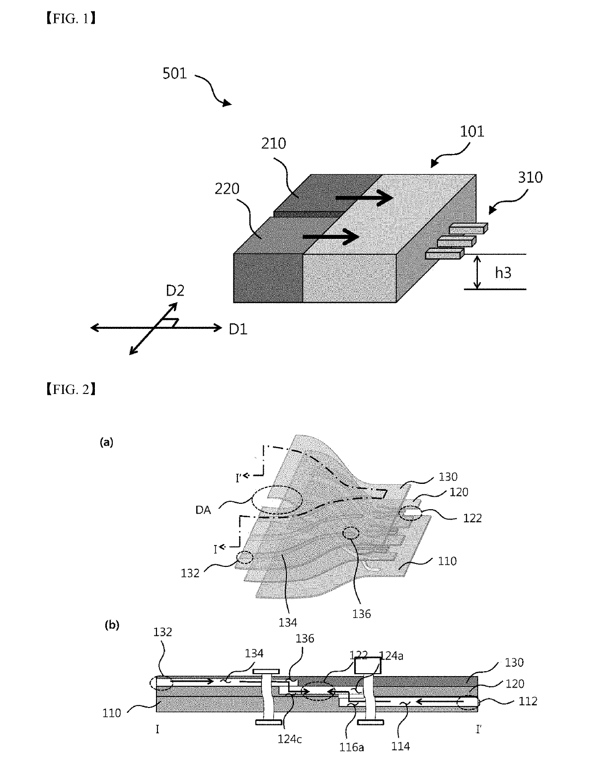
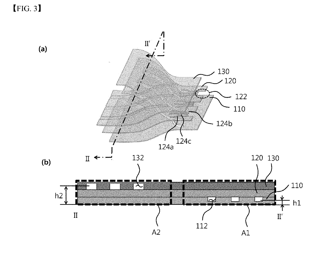
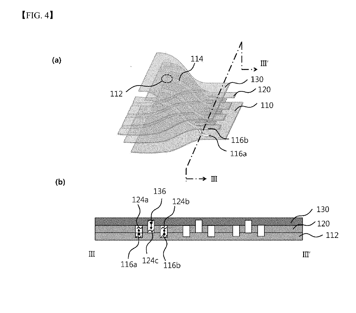
[0022]Examples of various embodiments are illustrated and described further below. It will be understood that the description herein is not intended to limit the claims to the specific embodiments described. On the contrary, it is intended to cover alternatives, modifications, and equivalents as may be included within the spirit and scope of the present disclosure as defined by the appended claims. In the following description, numerous specific details are set forth in order to provide a thorough understanding of the present disclosure. The present disclosure may be practiced without some or all of these specific details. In other instances, well-known process structures and / or processes have not been described in detail in order not to unnecessarily obscure the present disclosure. For simplicity and clarity of illustration, elements in the figures are not necessarily drawn to scale. The same reference numbers in different figures denote the same or similar elements, and as such per


PUM

PropertyMeasurementUnit
Lengthaaaaaaaaaa
Flow rateaaaaaaaaaa
Structureaaaaaaaaaa

Abstract

The present disclosure provides an apparatus for producing fine particles, the apparatus comprising: a particle formation mechanism and a particle-outlet micro-channel. The particle formation mechanism may include a unit-structure, wherein the unit-structure includes: first and second portions adjacent to each other; a first inlet defined in the first portion at a first height, wherein a continuous phase solution is injected into the first inlet; a second inlet defined in the first portion at a second height different from the second height, wherein a dispersed phase solution is injected into the second inlet; a merging volume defined in the second portion adjacent to the first portion, wherein the merging volume is defined at third height, wherein the third height is equal to either the first height and the second height, or has a value between the first height and the second height, wherein the continuous phase solution and the dispersed phase solution are merged in the merging volume, wherein fine particles are formed via the merging between the continuous phase solution and the dispersed phase solution in the merging volume; and a first micro-channel and a second micro-channel branching from the merging volume so as to be in communication with the first inlet and the second inlet, respectively.

Description


Claims


Application Information

Patent Timeline
Owner ENPARTICLE CO LTD
Why Eureka
Try Eureka