Unmanned underwater vehicle and method for controlling hydraulic system

Active Publication Date: 2019-07-11
FUGRO
View PDF2 Cites 1 Cited by
  • Summary
  • Abstract
  • Description
  • Claims
  • Application Information

AI Technical Summary

Benefits of technology

[0012]In some embodiments, the flow of hydraulic fluid through the flow restrictor does not cause actuating of any tools. For example the control valve being controlled as a function of a temperature controls a part of the hydraulic circuit separate from any of the actuated tools. Having a separate circuit, may have the advantage that the fluid can be kept circulating without undesired action by any of the tools. For example, one or more control valves may be controlled as a function of a temperature to control flow of hydraulic fluid through part of the hydraulic circuit separate from any hydraulic circuit through the actuated tools. For example, some control valves can be used for controlling a flow of hydraulic fluid for actuating the tools while other valves are controlled as a function of a temperature without actuating any tools. To prevent a deteriorated efficiency of the tools, the control valve to the flow restrictor may be closed while one or more control valves for operating the tools are open.
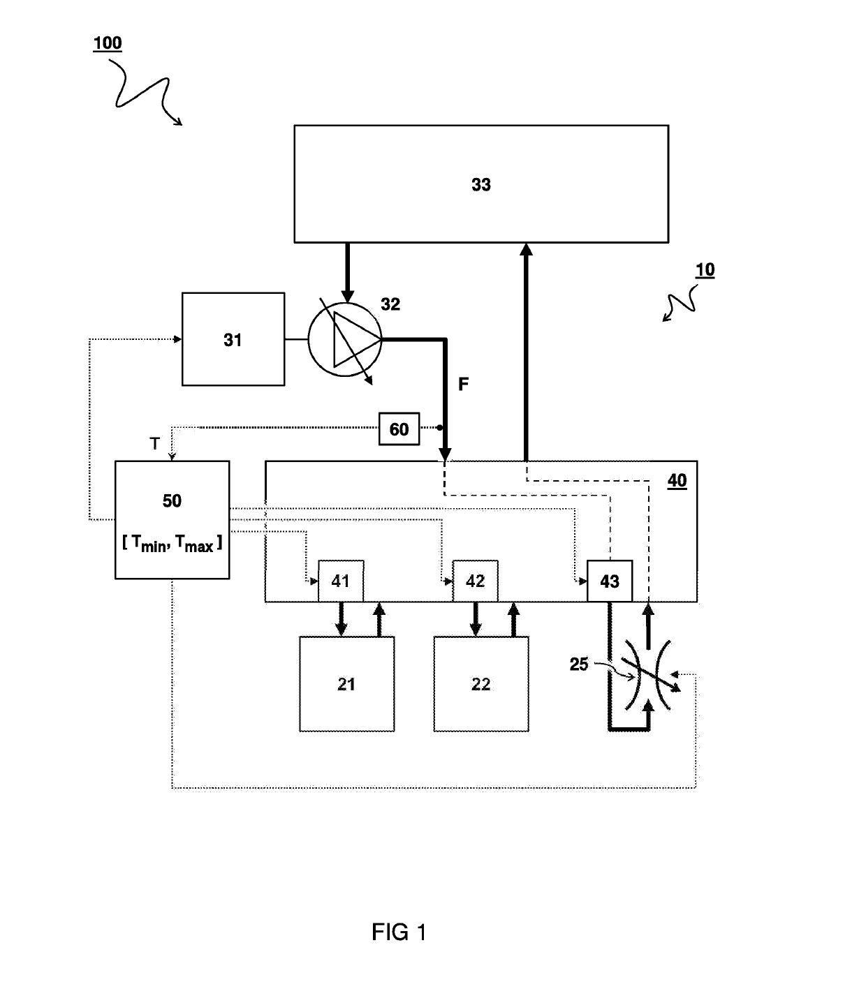
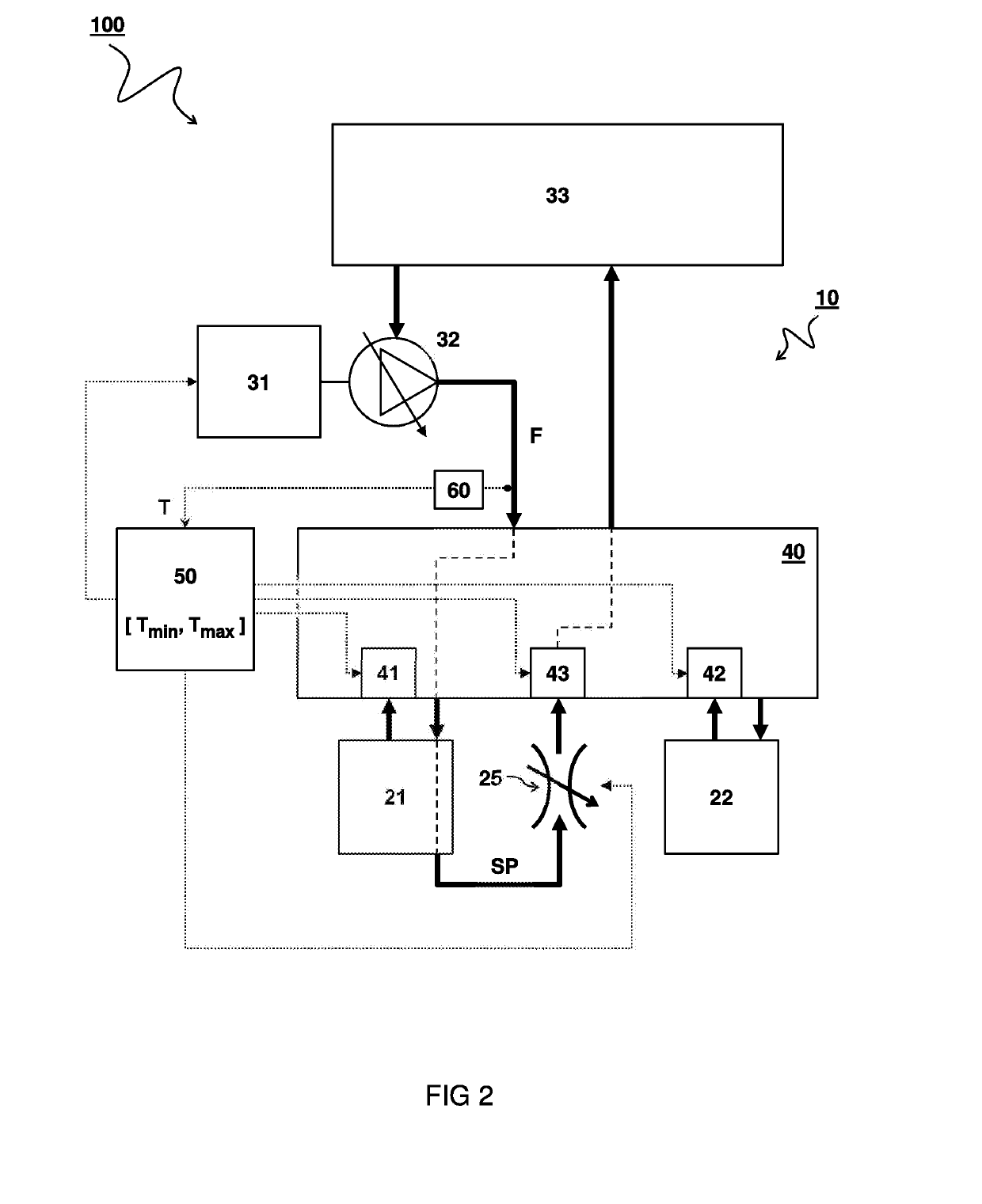
[0013]In other embodiment, a short-circuit path of hydraulic fluid partially traversing a path through one of the tools may be controlled as a function of temperature. For example, valves may be controlled for opening a short-circuit path of hydraulic fluid partially traversing through one of the tools when said one tool is not being actuated. In this way a circulation of fluid in the tool is maintained as much as possible while the short circuit path may prevent undesired actuating of the tool. The short-circuit path can be closed when it is desired to actuate the tool. For example, a tool comprises an actuating valve for actuating the tool by flowing hydraulic fluid through a regular actuating hydraulic circuit in the first tool and a short-circuit path with a separate control valve being controlled as a function of temperature. Accordingly, a flow of hydraulic fluid through at least part of the regular actuating circuit in the tool is maintained by opening the separate control valve when the tool is not being actuated. Optionally, the short-circuit path comprises a flow restrictor, e.g. mimicking a flow resistance that would be experienced through the regular path. In this way, the same friction and temperature increase can be maintained irrespective whether the tool is operated or not. Alternatively, the short-circuit path can have a relatively low resistance to save energy while still maintaining flow and preventing stagnant fluid.
[0014]To keep the amount of stagnant fluid as small as possible, it is preferred that a temperature control valve for maintaining a temperature of the hydraulic fluid is in proximity to an actuating control valve for actuating a tool. For example, the valve system comprises one or more flow control valves configured to maintain a flow of hydraulic fluid in at least fifty percent of the hydraulic circuit even when none of the tools are actuated, preferably at least eighty percent, more preferably at least ninety percent. By maintaining the flow of hydraulic fluid and preventing cooldown, it is not necessary to switch to low viscosity oils. Accordingly, the hydraulic fluid can have a normal or relatively high viscosity, e.g. higher than ISO22, preferably ISO Viscosity Grade 32 or higher.

Problems solved by technology

However, when operating in deep water conditions, the hydraulic fluid may be affected by cold surroundings and/or high pressure of the water.
In particular, when the hydraulic fluid cools down, the fluid may become thick and difficult to move through the hydraulic circuit, especially if the fluid has become stagnant when a tool is not used for some time.
However, using low viscosity oil may affect operation at relatively high temperature conditions.
However, the heating mechanisms available underwater such as, e.g., electrical heating under water may consume too much power and could present failures, such as short circuits.
In this manner, the circulation of hydraulic fluid may in itself result in heating of the fluid, e.g. by friction and/or pump action.

Method used


Image

  • Unmanned underwater vehicle and method for controlling hydraulic system
  • Unmanned underwater vehicle and method for controlling hydraulic system

Examples


Example

[0019]In some instances, detailed descriptions of well-known devices and methods may be omitted so as not to obscure the description of the present systems and methods. Terminology used for describing particular embodiments is not intended to be limiting of the invention. As used herein, the singular forms “a”, “an” and “the” are intended to include the plural forms as well, unless the context clearly indicates otherwise. The term “and / or” includes any and all combinations of one or more of the associated listed items. It will be understood that the terms “comprises” and / or “comprising” specify the presence of stated features but do not preclude the presence or addition of one or more other features. It will be further understood that when a particular step of a method is referred to as subsequent to another step, it can directly follow said other step or one or more intermediate steps may be carried out before carrying out the particular step, unless specified otherwise. Likewise


PUM


Abstract

An unmanned underwater vehicle (UUV) with a hydraulic system (100) for use in cold surroundings and method of controlling such hydraulic system. The hydraulic system (100) comprises a hydraulic circuit (10). One or more tools (21,22) may be hydraulically operable via the hydraulic circuit (10). A pump (32) is configured to pressurize a flow of hydraulic fluid (F) via the hydraulic circuit (10) e.g. for actuating the tools (21,22). A valve system (40) comprises control valves (41,42,43) disposed in the hydraulic circuit (10) for controlling the flow of hydraulic fluid (F) through the hydraulic circuit (10). A controller (50) is configured to control one or more of the control valves (43) as a function of a temperature (T) of the hydraulic fluid (F).

Description


Claims


Application Information

Patent Timeline
Owner FUGRO
Why Eureka
Try Eureka