Radio frequency circuit, multiplexer, radio frequency front end circuit and communication apparatus
a radio frequency front end circuit and radio frequency circuit technology, applied in the direction of tunable filters, gated amplifiers, filters, etc., can solve the problems of unnecessary electromagnetic field coupling between both wirings, transmission characteristic of radio frequency signal passing between the first input/output terminal and the second input/output terminal, etc., to suppress the deterioration of insertion loss, the effect of low loss and high attenuation
- Summary
- Abstract
- Description
- Claims
- Application Information
AI Technical Summary
Benefits of technology
Problems solved by technology
Method used
Image

Examples
first embodiment
[0062][1.1 Configuration of Radio Frequency Circuit]
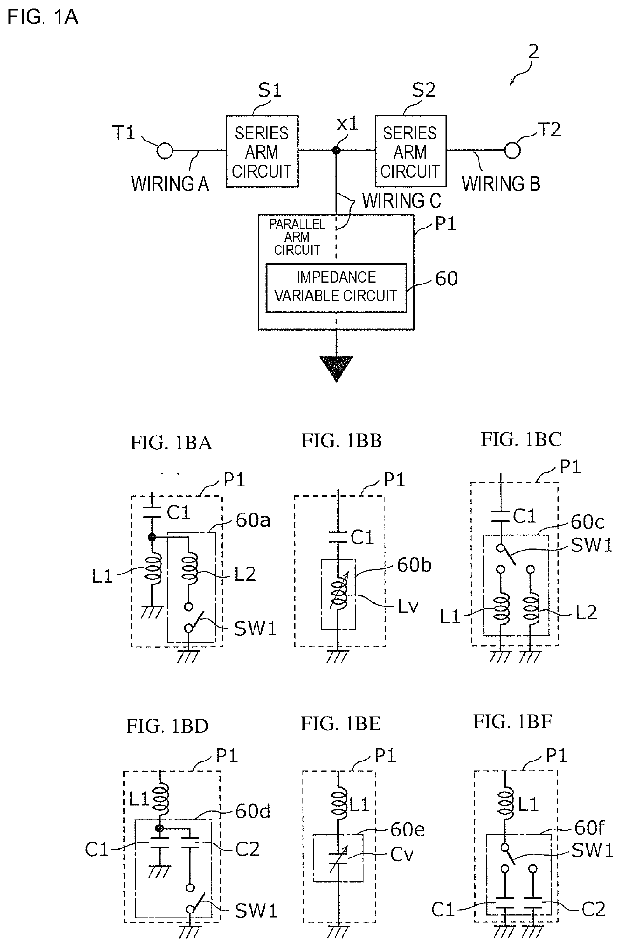
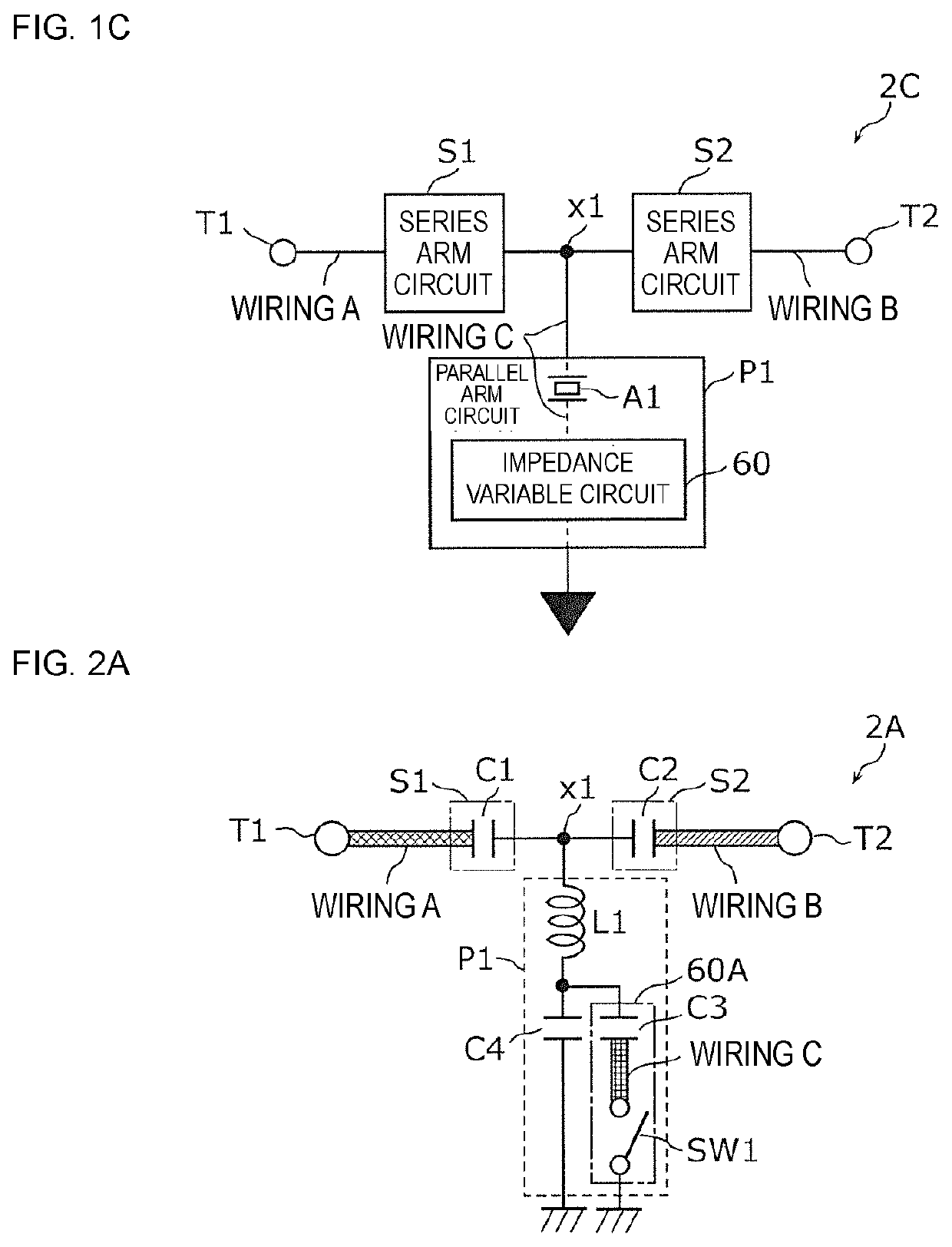
[0063]FIG. 1A is a circuit configuration diagram of a radio frequency circuit 2 according to the first embodiment. The radio frequency circuit 2 illustrated in the figure includes input / output terminals T1 and T2, series arm circuits S1 and S2, and a parallel arm circuit P1.
[0064]The series arm circuit S1 is a first series arm circuit arranged in a first path connecting the input / output terminal T1 (first input / output terminal) and the input / output terminal T2 (second input / output terminal). In addition, the series arm circuit S2 is a second series arm circuit arranged in the first path connecting the input / output terminal T1 and the input / output terminal T2. The series arm circuit S1 and the series arm circuit S2 are arranged in series in the first path, and are configured by passive elements such as inductors and capacitors.
[0065]The parallel arm circuit P1 is arranged in a second path connecting a node x1 and the grou
second embodiment
[0141]In this embodiment, a multiplexer 10, a radio frequency front end circuit 50, and a communication apparatus 1 using the radio frequency circuit 2 according to the first embodiment will be described.
[0142][2.1 Configuration of Communication Apparatus]
[0143]FIG. 6A is a circuit configuration diagram of the communication apparatus 1 according to the second embodiment. As illustrated in FIG. 6A, the communication apparatus 1 includes an antenna element 3, the radio frequency front end circuit 50, an RF signal processing circuit (RFIC) 4, and a baseband signal processing circuit (BBIC) 5.
[0144]The RFIC 4 is an RF signal processing circuit for processing a radio frequency signal transmitted and received by the antenna element 3. Specifically, the RFIC 4 performs signal processing of a radio frequency signal (here, a radio frequency reception signal) input from the antenna element 3 with the radio frequency front end circuit 50 interposed therebetween by down-conversion or the like, and
third embodiment
[0178]In the second embodiment, one of the plurality of filters configuring the multiplexer is a frequency variable filter, whereas the multiplexer according to this embodiment has a configuration in which two of the plurality of filters configuring the multiplexer are frequency variable filters.
[0179][3.1 Configuration of Radio Frequency Front End Circuit]
[0180]FIG. 8 is a circuit configuration diagram of a radio frequency front end circuit 50L according to a third embodiment and its peripheral circuit. As illustrated in this figure, the radio frequency front end circuit 50L is a reception system front end circuit, and includes a multiplexer 10L, switches 31L and 32L, filters 21L, 22L, 23L, 24L, and 25L, and reception amplifiers 41L, 42L, 43L, 44L, and 45L.
[0181]The multiplexer 10L includes the common terminal 100, the input / output terminals 110 and 120, a low pass filter 11L, and a high pass filter 12L.
[0182]The low pass filter 11L is a low pass type filter in which the radio frequ
PUM
 Abstract
Description
Claims
Application Information
 - R&D Engineer
- R&D Manager
- IP Professional
- Industry Leading Data Capabilities
- Powerful AI technology
- Patent DNA Extraction
Browse by: Latest US Patents, China's latest patents, Technical Efficacy Thesaurus, Application Domain, Technology Topic.
© 2024 PatSnap. All rights reserved.Legal|Privacy policy|Modern Slavery Act Transparency Statement|Sitemap