Resistive charcoal igniter system and method

Inactive Publication Date: 2020-09-03
GRANTHAM CHARLES GARY
View PDF6 Cites 0 Cited by
  • Summary
  • Abstract
  • Description
  • Claims
  • Application Information

AI Technical Summary

Benefits of technology

[0006]Because of the disadvantages inherent in the known charcoal ignition art, the present disclosure provides a novel resistive charcoal igniter syste

Problems solved by technology

However, many people avoid charcoal-fired barbecue cooking simply because they find it difficult, messy, or inconvenient.
In particular, lighting the charcoal can present a dreaded chore for many.
Charcoal, lump charcoal, or charcoal briquets can be difficult to light merely using a match or other light flame sources, and lighting the charcoal in the basin underneath the barbecue grill may also be messy.
Flammable fluids may make lighting easier bu

Method used


Image

  • Resistive charcoal igniter system and method
  • Resistive charcoal igniter system and method
  • Resistive charcoal igniter system and method

Examples


Embodiment Construction

[0015]As discussed above, embodiments of the present disclosure relate to a fuel lighter and more particularly to a resistive charcoal igniter system and method as used to improve the lighting of charcoal, lump charcoal, or charcoal briquets for a barbecue.

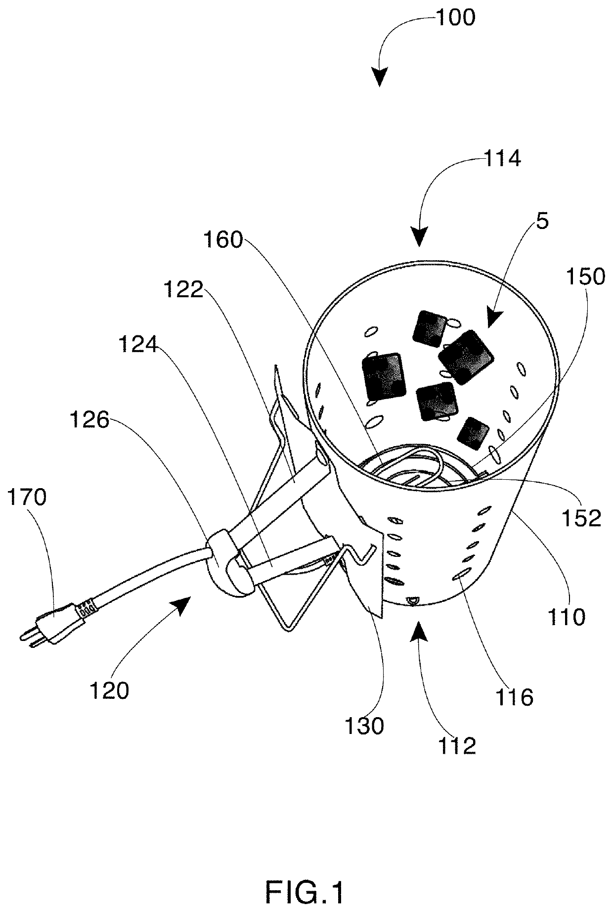
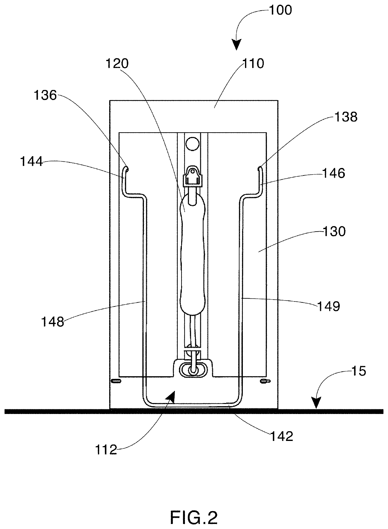
[0016]The resistive charcoal igniter system includes a device for containing and igniting charcoal, lump charcoal, or charcoal briquets. The device includes a cylindrical container with a wire base in the bottom for containing the charcoal. The cylinder may be constructed of galvanized sheet steel and have apertures providing ventilation and airflow.

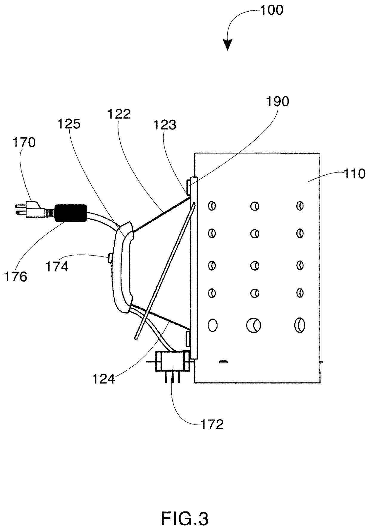
[0017]An electrically operated heating element is located within the wire base. When charcoal is placed in the container, and the heating element is energized, the charcoal, lump charcoal, or charcoal briquets ignite after enough time. The device also includes a handle affixed to the container and a heatshield placed between the handle and the container to protect a user's hand from heat


PUM


Abstract

Disclosed is a resistive charcoal igniter device for containing and igniting charcoal, lump charcoal, or charcoal briquets. The device has a cylindrical container with a wire base or grates in the bottom for containing the charcoal. An electrically operated heating element is located within the wire base. When charcoal is placed in the container, and the heating element is energized, the charcoal, lump charcoal, or charcoal briquets can be ignited after a sufficient time. The device also includes a handle affixed to the container and a heatshield placed between the handle and the container to protect a user's hand from heat generated within the container while holding the handle. The resistive heater is powered externally and may be electrically connected to a power source by an extension cord integrated into the device.

Description


Claims


Application Information

Patent Timeline
Owner GRANTHAM CHARLES GARY
Why Eureka
Try Eureka