Anti-contamination needle removing device

Inactive Publication Date: 2020-10-08
COREBIO TECH CO LTD
View PDF0 Cites 0 Cited by
  • Summary
  • Abstract
  • Description
  • Claims
  • Application Information

AI Technical Summary

Benefits of technology

[0004]In view of the above, the present invention provides a needle removing device suitable for removing needles of all sizes, and totally and effectively separating needles without causing air dust pollution, thus preventing substances from being splashed to the outside of the device during the process of needle removal.

Problems solved by technology

However, whether a patient has an infectious disease is unknown before such blood test, and thus, in order to prevent cross-infection, a needle can used only once instead of being repeatedly used.
During the process of recycling or handling, accidents of medical staff inadvertently being pricked by needles are inevitable, resulting in physical wounds in minor cases, or infection by residual virus or bacteria on the needles in more severe cases.
However, due to different lengths and thicknesses of needles, such current needle removing device may not be suitable for needles of various sizes.
Furthermore, while the device removes a needle, a function of totally and effectively removing an iron element and a plastic element cannot be achieved.
Also, some needle removing devices adopt a cutting means, but which does not totally and effectively separate an iron element and a plastic element.
However, such melting means can cause possible air dust pollution, and unavoidably leads to residual blood, body fluid or splashed glue on the needles.
The splashed or stirred substances can not only result in environmental pollution but also splash on medical staff, bringing about risks of disease infection.

Method used


Image

  • Anti-contamination needle removing device
  • Anti-contamination needle removing device
  • Anti-contamination needle removing device

Examples


Example

[0026]It is to be noted that, unless otherwise specified, the technical and scientific terms used herein refer to common meanings generally understood by a person skilled in the art. Furthermore, the term “a” used in the description refers to a quantity of at least one (one or more) unless otherwise specified. It should also be noted that, the descriptive terms related to orientation (e.g., “front”, “back”, “upper”, and “lower”, etc.) used in the description are illustrative or relative terms which need to be conceptively adjusted according to different users or different usages, and are not enumerative or absolute terms.

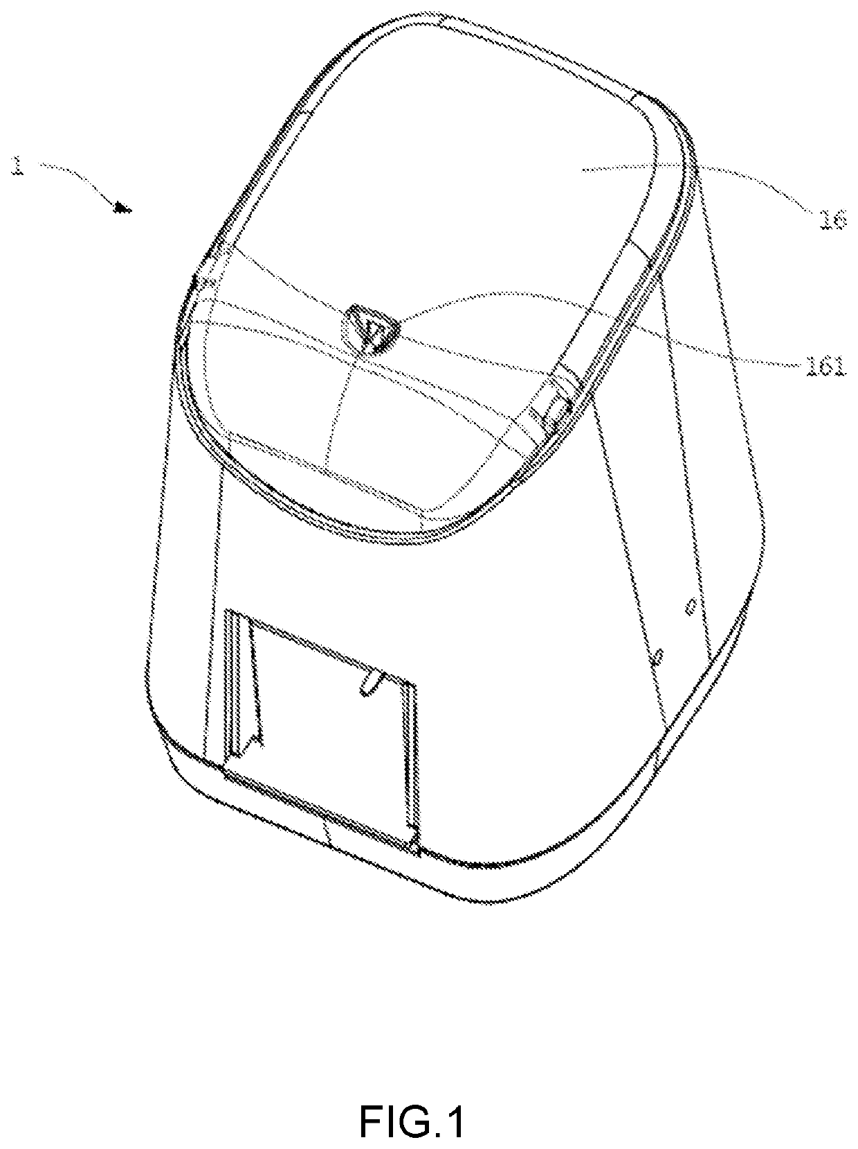
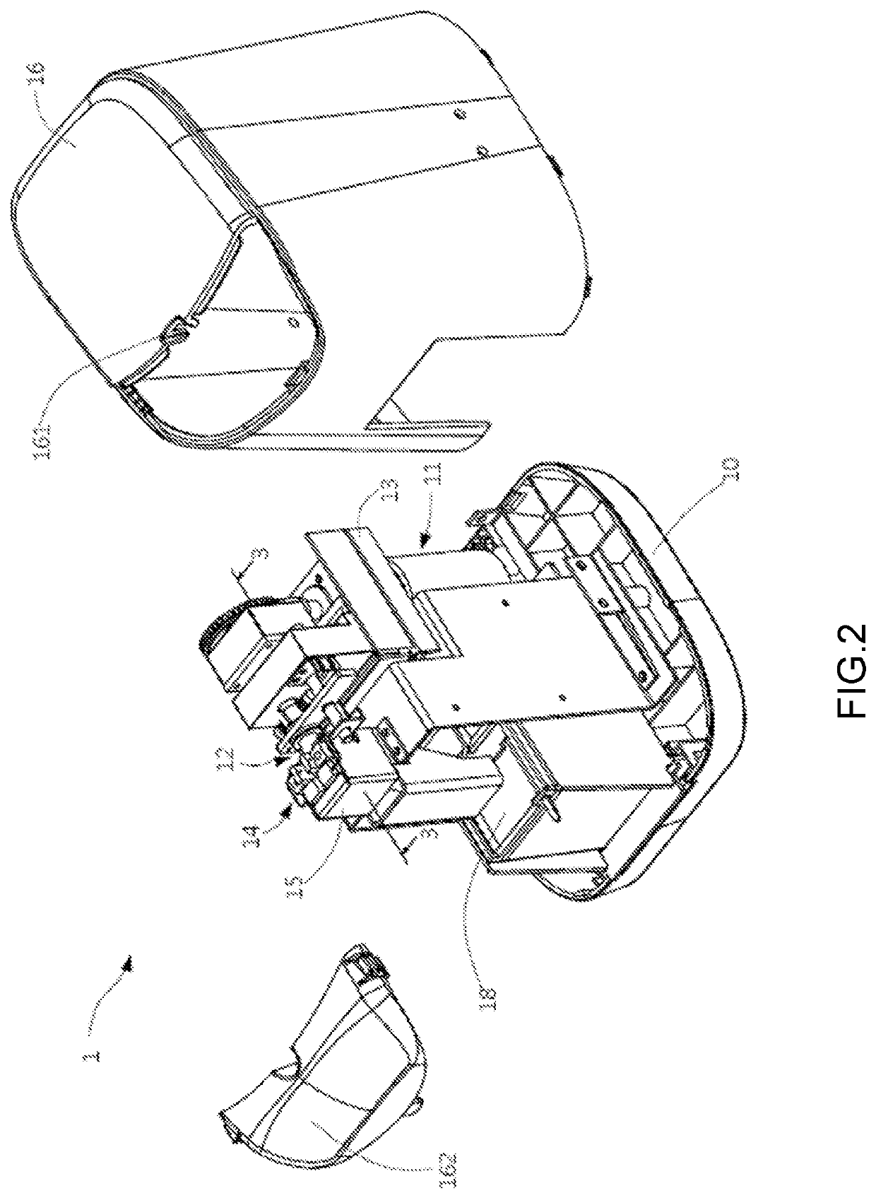
[0027]Referring to FIG. 1 and FIG. 2, FIG. 1 shows a perspective schematic diagram of a needle removing device 1 according to an embodiment of the present invention, and FIG. 2 shows an exploded schematic diagram of partial components of the needle removing device 1 according to an embodiment of the present invention. In this embodiment, the needle removing device 1 is


PUM


Abstract

A needle removing device includes a seat, a driving assembly, a removal assembly and a lift assembly. The driving assembly is disposed on the seat. The removal assembly has one end thereof connected to one end of the driving assembly away from the seat, and includes a needle winding member and a pressing member. The needle winding member is located on one end of the removal assembly away from the driving assembly. The pressing member is connected to the needle winding member. The lift assembly is disposed on the seat. The driving assembly and the removal assembly are movable relative to the seat via the lift assembly. The needle winding member includes a first rod and a second rod, wherein the first rod and the second rod are adjacently spaced to form a disassembly space. The pressing member includes a first elastic element and a second elastic element. The first elastic element is connected to the first rod, the second elastic element is connected to the second rod, and the first elastic element and the second elastic element cause the first rod and the second rod to be inclined close to each other. The first elastic element and the second elastic element cause the first rod and the second rod to clamp the needle, and the first rod and the second rod rotate to wind the needle.

Description


Claims


Application Information

Patent Timeline
Owner COREBIO TECH CO LTD
Why Eureka
Try Eureka