Liquid transfer device and method of use

Active Publication Date: 2020-10-22
MCKINNEY KEVIN D +1
View PDF0 Cites 0 Cited by
  • Summary
  • Abstract
  • Description
  • Claims
  • Application Information

AI Technical Summary

Benefits of technology

[0008]Technical effects of the device and method described above preferably include the ability to transfer liquids between contai

Problems solved by technology

However, contact between the funnel and the liquid often leads to waste since at least some of the liquid will likely remain on the funnel and require cleaning.
This is especially an issue for relatively viscous liquids such as hand soaps, which typically leave a thick film on the funnel.
During

Method used


Image

  • Liquid transfer device and method of use
  • Liquid transfer device and method of use
  • Liquid transfer device and method of use

Examples


Embodiment Construction

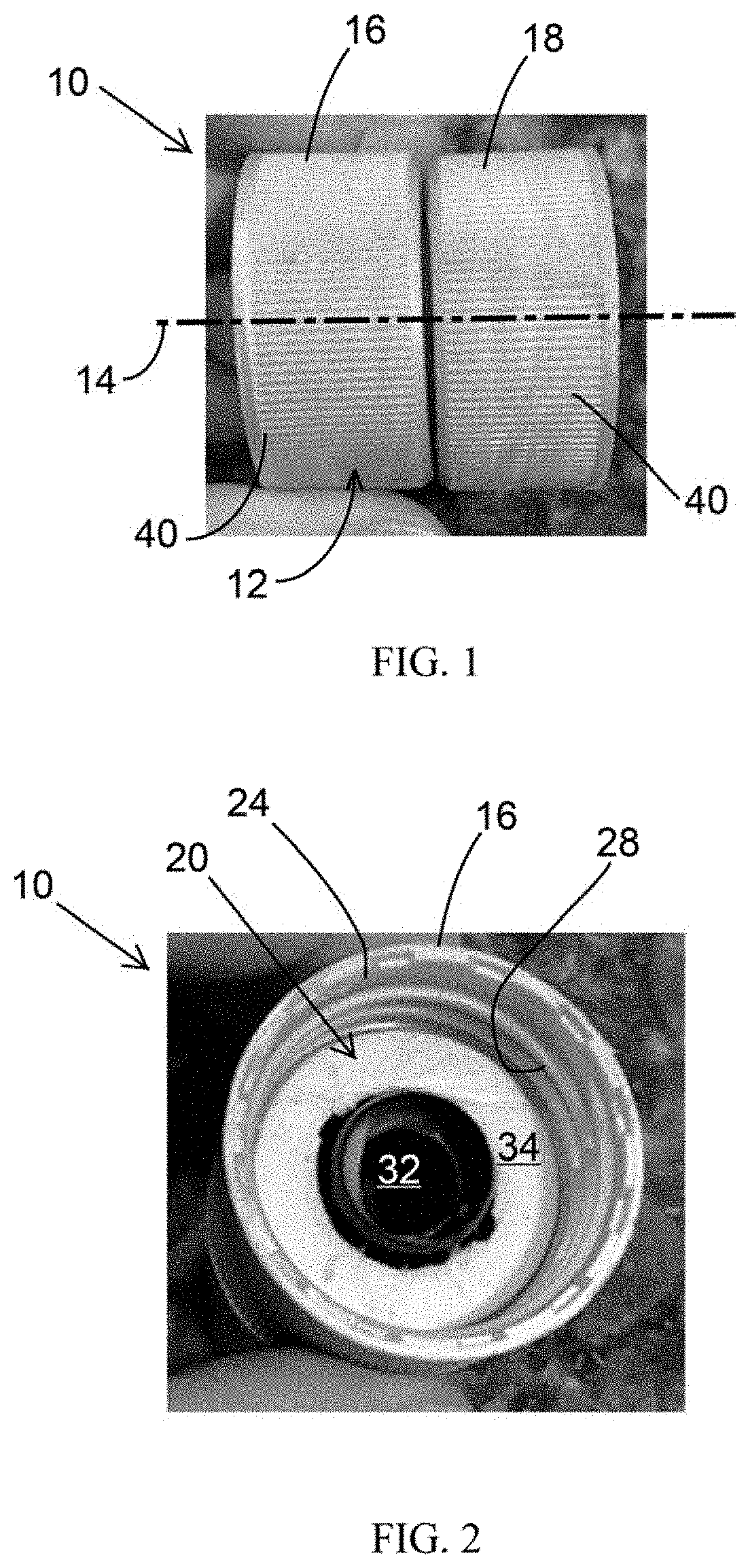
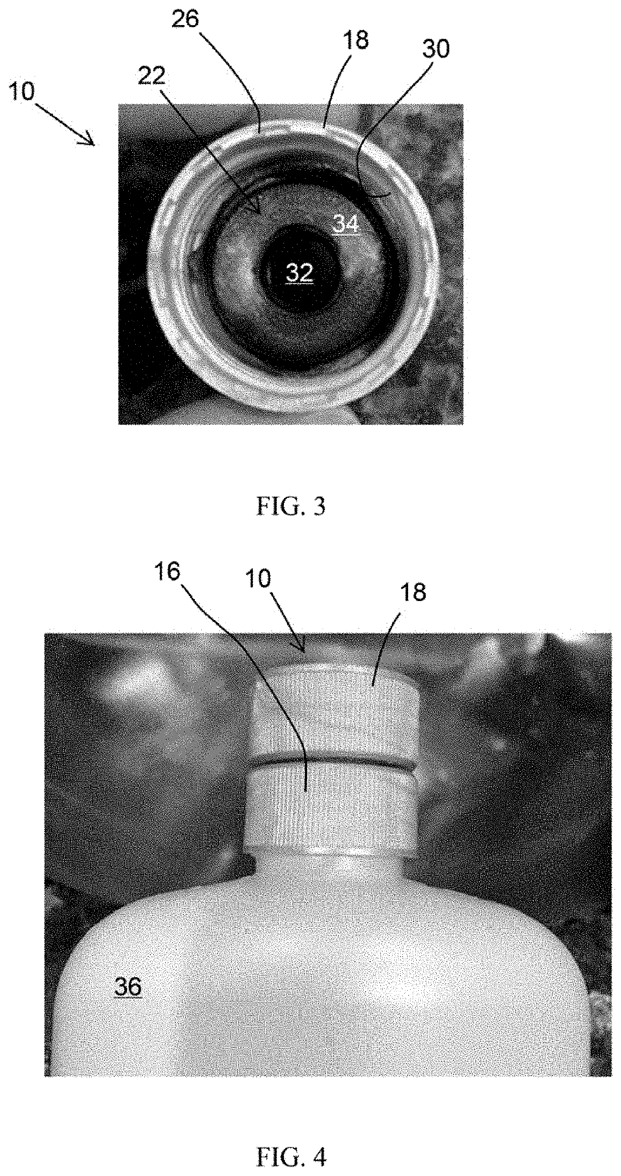
[0013]FIGS. 1 through 3 schematically represent a nonlimiting embodiment of a liquid transfer device 10. The device 10 includes a generally cylindrical body 12 that defines an axis 14 of the device 10. The body 12 comprises first and second cap members 16 and 18 that are disposed at opposite axial ends of the body 12. As seen in FIGS. 2 and 3, each cap member 16 and 18 defines an interior cavity 20 and 22, respectively, each defining an axial opening 24 and 26 at a respective axial end of the body 12. The cavities 20 and 22 are coaxially aligned along the axis 14 of the body 12 and define interior walls within the cap members 16 and 18 on which female threads 28 and 30, respectively, are formed. The female threads 28 and 30 may have identical or different diameters and thread pitches, depending on the types of containers for which the device 10 is intended to be used.

[0014]A fluid passage 32 within the body 12 fluidically interconnects the cavities 20 and 22 of the cap members 16 and 1


PUM


Abstract

A device for transferring liquids from between containers, and methods for its use. The device includes a body having an axis and first and second cap members at oppositely-disposed axial ends of the body. Cavities are present within the first and second cap members and define axial openings in the body. The cavities are coaxially aligned along the axis of the body and define interior walls within the first and second cap members on which female threads are formed. At least one fluid passage is within the body and fluidically interconnects the cavities. The axial openings in the body are configured to receive necks of first and second containers, and the female threads are configured to couple with male threads on the necks of the first and second containers such that the device physically couples the first and second containers together

Description


Claims


Application Information

Patent Timeline
Owner MCKINNEY KEVIN D
Why Eureka
Try Eureka