Stretchable thermal radiation modulation system via mechanically tunable surface emissivity
- Summary
- Abstract
- Description
- Claims
- Application Information
AI Technical Summary
Benefits of technology
Problems solved by technology
Method used
Image

Examples
example 1
adiation Modulation System—In-Plane Uniaxial Strain Test (TMSU)
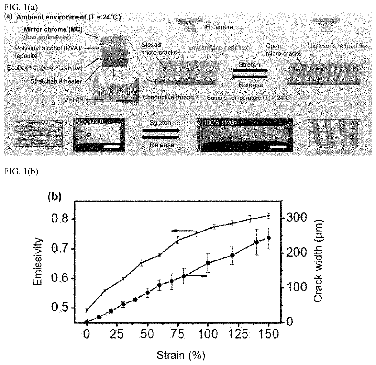
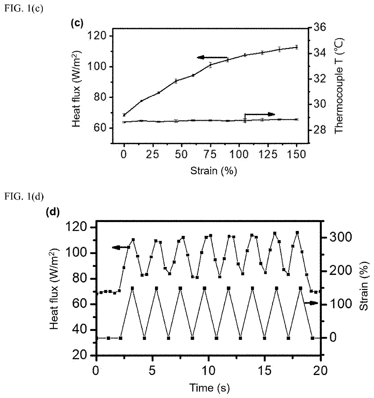
[0053]The following is an exemplary preparation of the thermal radiation modulation system for the in-plane uniaxial strain test (TMSU). A layer of PVA (KURARAY POVAL™ 28-99, MW (weight average molecular weight) ˜145,000) and laponite (BYK Additives Inc., Gonzales, Tex., USA, mass ratio of PVA to laponite=3:2) composite films with a thickness of ca. 297 nm were cast on a pre-cleaned foundation (using a 5 mg / mL PVA / laponite aqueous solution) followed by the treatment of allyl isocyanate. The Ecoflex® 00-30 precursors (The Ecoflex® studied in this work all contains Part A and Part B with a weight ratio=1:1, Smooth-On, Inc.; Ecoflex® 00-30 is a platinum-catalyzed silicone) was cast atop the allyl isocyanate treated PVA film followed by curing at 80° C. for 2 hours (thickness of the Ecoflex® layer≈1.5 mm). The bilayer materials was then peeled off from the foundation and cut into a rectangle shape followed by sprayed coatin
example 2
Thermal Radiation Modulation System for Out-of-Plane Bulging Strain Test (TMSB)
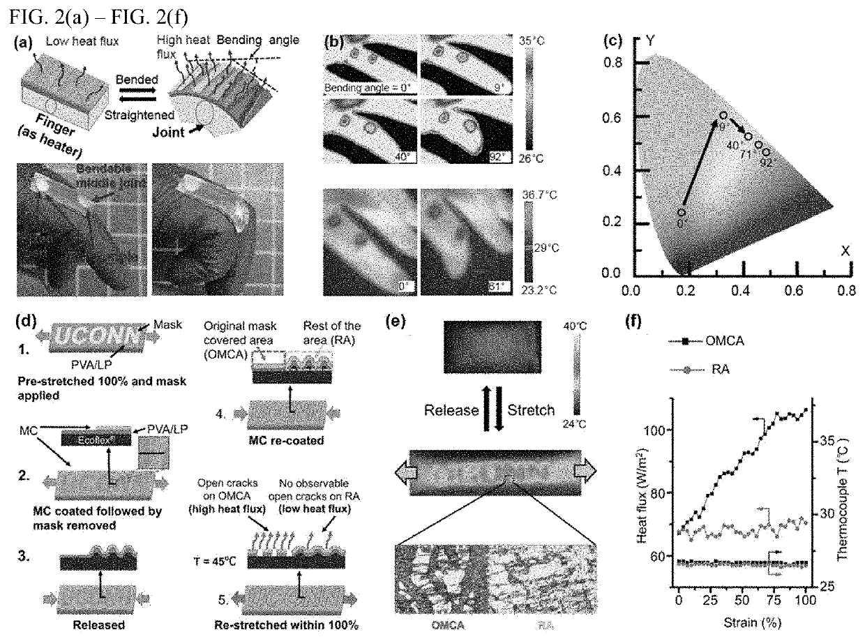
[0065]The following is an exemplary preparation of the thermal radiation modulation system for bulging strain test (TMSB) for dynamic display and thermal camouflage. The preparation steps for the PVA / laponite and Ecoflex® layer was the same as aforementioned procedure in Example 1. The bilayer was then cutting into a circular shape with a diameter of 5 cm after peeled away from foundation. A layer of mirror chrome (thickness≈310 nm) was then spray coated atop the PVA / laponite layer. Since the peeling process will introduce cracks perpendicular to peeling direction on the MC and the PVA / laponite rigid thin film, a pre-stretched uniaxial strain of 100% was applied in the direction perpendicular to original crack orientation followed by another 100% uniaxial strain applied on direction aligned with the crack orientation prior to released back 0% strain. Thus, two type distributed cracks vertical to each o
PUM
| Property | Measurement | Unit |
|---|---|---|
| Fraction | aaaaa | aaaaa |
| Tensile strain | aaaaa | aaaaa |
| Tensile strain | aaaaa | aaaaa |
Abstract
Description
Claims
Application Information
 - R&D Engineer
- R&D Manager
- IP Professional
- Industry Leading Data Capabilities
- Powerful AI technology
- Patent DNA Extraction
Browse by: Latest US Patents, China's latest patents, Technical Efficacy Thesaurus, Application Domain, Technology Topic.
© 2024 PatSnap. All rights reserved.Legal|Privacy policy|Modern Slavery Act Transparency Statement|Sitemap