Spintronics element and magnetic memory device

Pending Publication Date: 2022-05-12
THE UNIV OF TOKYO
View PDF0 Cites 0 Cited by
  • Summary
  • Abstract
  • Description
  • Claims
  • Application Information

AI Technical Summary

Benefits of technology

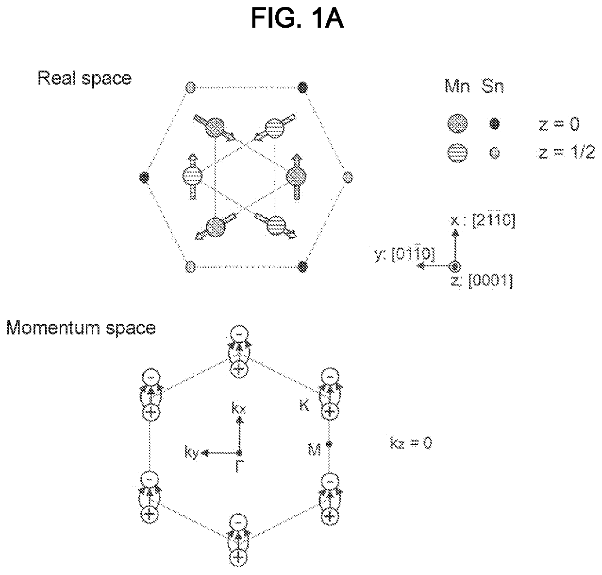
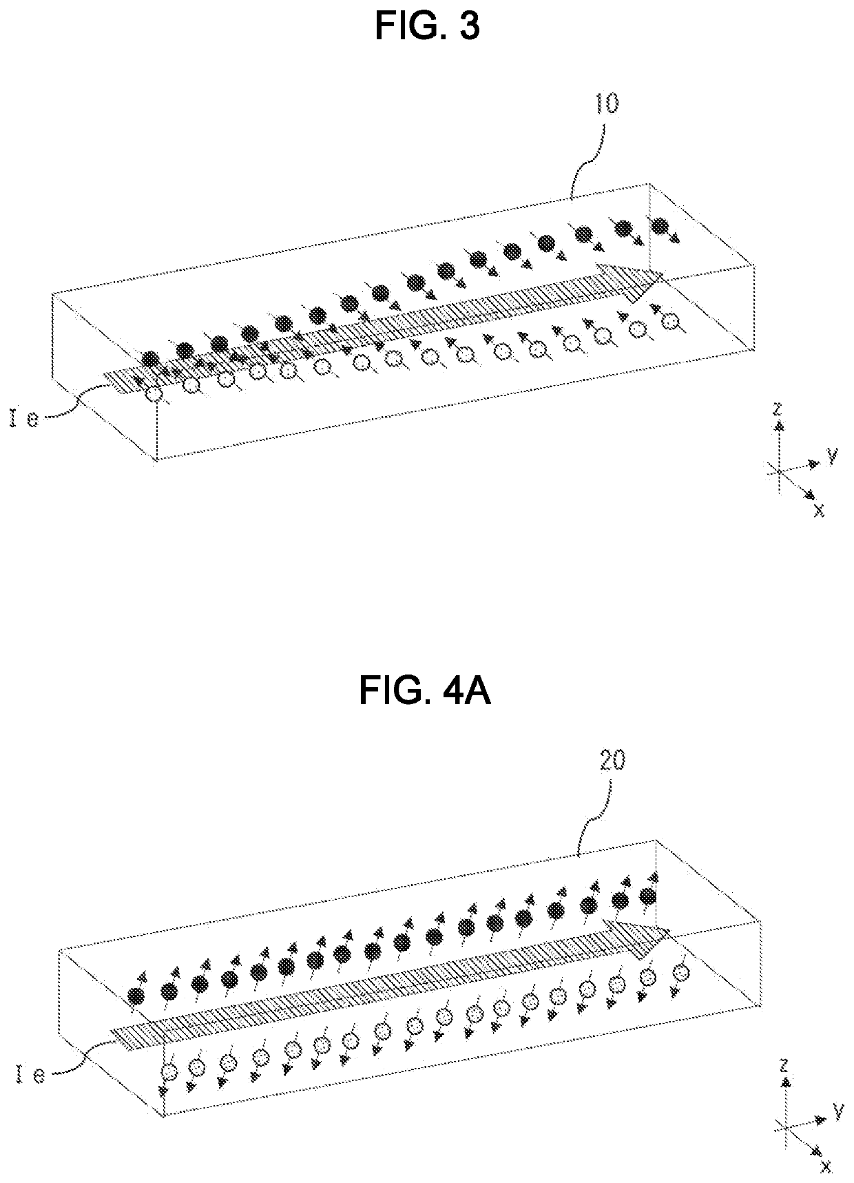
[0013]According to the present invention, spin accumulation is generated in an antiferromagnetic layer made of a canted antiferromagnet such that spins of electrons are spin-polarized parallel to or obliquely to an out-of-plane direction. This enables reversal of perpendicular magnetization in a ferromagnet stacked on the antiferromagnetic layer at zero magnetic field without exchange bias.

Problems solved by technology

In STT-MRAM, however, read and write operations share the same current path, which results in reducing writing endurance.
Thus, the magnetization reversal occurs along the anisotropic path in SOT-MRAM with in-plane magnetization, which is highly likely to exhibit complicated precession of magnetization and cause write error.

Method used


Image

  • Spintronics element and magnetic memory device
  • Spintronics element and magnetic memory device
  • Spintronics element and magnetic memory device

Examples


Example

[0025]Exemplary embodiments of the present invention will be described below with reference to the drawings. The same reference signs are used to designate the same or similar components throughout the drawings.

[0026]Ferromagnets exhibit a relatively large magnetization, and thus have been used extensively as key components of various devices including motors, power generators, magnetic sensors, and magnetic memories. Antiferromagnets, on the other hand, exhibit a very tiny magnetization, show an extremely small response, and are hard to control as opposed to ferromagnets, which leads to limited applications.

[0027]In recent years, spintronics for magnetic memories has required high density and high-speed processing. A memory cell with an antiferromagnetic component produces almost no stray fields because of a tiny magnetization described above. Therefore, antiferromagnets would be suitable for use in high-density magnetic memories. Moreover, antiferromagnets typically have a resonant f


PUM


Abstract

A spintronics element (100) includes an antiferromagnetic layer (20) and an MTJ element (30). The antiferromagnetic layer (20) is made of a canted antiferromagnet having a canted magnetic moment to exhibit a relatively tiny magnetization, and allows an electric current flowing in one direction (y-axis direction) parallel to an in-plane direction to induce spin accumulation in which spins of electrons are polarized parallel to or obliquely to an out-of-plane direction (z-axis direction). The MTJ element (30) is stacked on the antiferromagnetic layer (20), contains a ferromagnet with a magnetization (M11) aligned with the out-of-plane direction that is a stacking direction, and allows a spin current generated in the antiferromagnetic layer (20) to exert a spin-orbit torque on the magnetization (M11), thereby causing reversal of the magnetization (M11).

Description


Claims


Application Information

Patent Timeline
Owner THE UNIV OF TOKYO
Why Eureka
Try Eureka