Current sensor
A current sensor, a technology for measuring current, applied in the direction of only measuring current, voltage/current isolation, instruments, etc., can solve the problem of current detection accuracy decline, and achieve the effect of suppressing the decrease in detection accuracy
- Summary
- Abstract
- Description
- Claims
- Application Information
AI Technical Summary
Benefits of technology
Problems solved by technology
Method used
Image

Examples
no. 1 Embodiment approach
[0062]
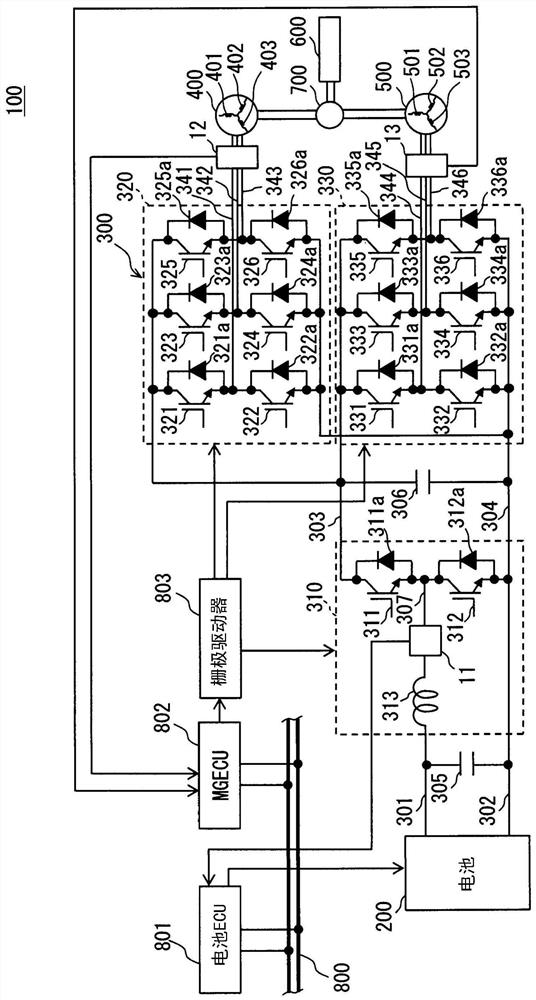
[0063] First, the in-vehicle system 100 to which the current sensor is applied will be described. The in-vehicle system 100 constitutes a hybrid system. Such as figure 1 As shown, the in-vehicle system 100 has a battery 200 , a power conversion device 300 , a first motor 400 , a second motor 500 , an engine 600 , and a power distribution mechanism 700 .
[0064] Furthermore, the in-vehicle system 100 has a plurality of ECUs. figure 1 In FIG. 2 , battery ECU 801 and MGECU 802 are shown as representatives of these plural ECUs. These plurality of ECUs exchange signals with each other via the bus wiring 800 to coordinately control the hybrid vehicle. Through this coordinated control, the regeneration and power operation of the first motor 400 , the power generation of the second motor 500 , the output of the engine 600 , and the like are controlled according to the SOC of the battery 200 . SOC is the abbreviation of state of charge (state of charge). ECU is the abbrev
no. 2 Embodiment approach
[0384] Next, based on Figure 26 and Figure 27 The second embodiment will be described. The current sensors of the embodiments described below have many points in common with the current sensors of the above-described embodiments. Therefore, the description of the common parts will be omitted below, and the different parts will be emphasized. In addition, the same code|symbol is attached|subjected to the same element as the element shown in the said embodiment below.
[0385]
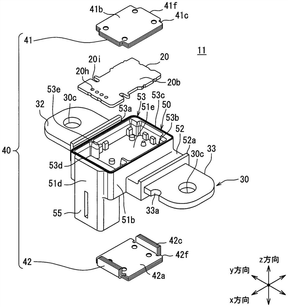
[0386] In the first embodiment, an example is shown in which the extending portion 42c extending in the z direction is formed on the second central portion 42d side of each of the two end sides 42f aligned in the x direction of the second shielding portion 42 . In contrast, in this embodiment, if Figure 26 As shown, an extended portion 42c is formed on the second end portion 42e side of each of the two end sides 42f of the second shield portion 42 . Figure 26 Column (a) is a perspective view for
no. 3 Embodiment approach
[0399] Next, based on Figure 30 ~ Figure 32 The third embodiment will be described.
[0400]
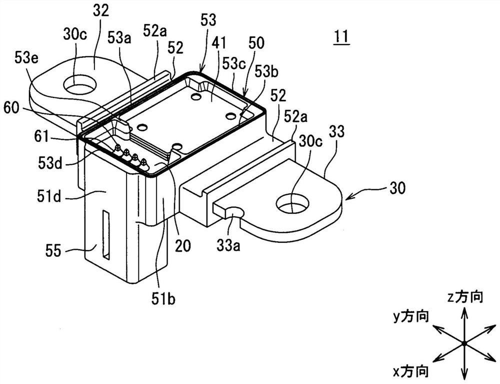
[0401] In the present embodiment, the stress relaxation portion 34 is formed on the conductive bus bar 30 of the first current sensor 11 . The stress relieving portions 34 are respectively formed on the first exposed portion 32 and the second exposed portion 33 of the conductive bus bar 30 .
[0402] As described above, the conductive bus bar 30 has the covering portion 31 covered by the sensor case 50 . The first exposed portion 32 and the second exposed portion 33 are respectively exposed from the sensor case 50 and are integrally connected to the covering portion 31 . Further, bolt holes 30c through which bolts are inserted to electrically and mechanically connect to the current bus bar 307 are respectively formed in the first exposed portion 32 and the second exposed portion 33 . The stress relieving portion 34 is formed between the connecting portion of the first exposed port
PUM
 Abstract
Description
Claims
Application Information
 - R&D Engineer
- R&D Manager
- IP Professional
- Industry Leading Data Capabilities
- Powerful AI technology
- Patent DNA Extraction
Browse by: Latest US Patents, China's latest patents, Technical Efficacy Thesaurus, Application Domain, Technology Topic.
© 2024 PatSnap. All rights reserved.Legal|Privacy policy|Modern Slavery Act Transparency Statement|Sitemap